
Mobile communication system and signal processing method thereof

Active Publication Date: 2004-12-30
AEGIS 11 SA
View PDF3 Cites 99 Cited by
  • Summary
  • Abstract
  • Description
  • Claims
  • Application Information

AI Technical Summary

Benefits of technology

[0007] Accordingly, one object of the present invention is to solve at least the above problems and / or disadvantages and to provide at least the advantages described hereinafter.

Problems solved by technology

This independence, however, is not always maintained resulting in data not being properly detected.

Method used


Image

  • Mobile communication system and signal processing method thereof
  • Mobile communication system and signal processing method thereof
  • Mobile communication system and signal processing method thereof

Examples


Embodiment Construction

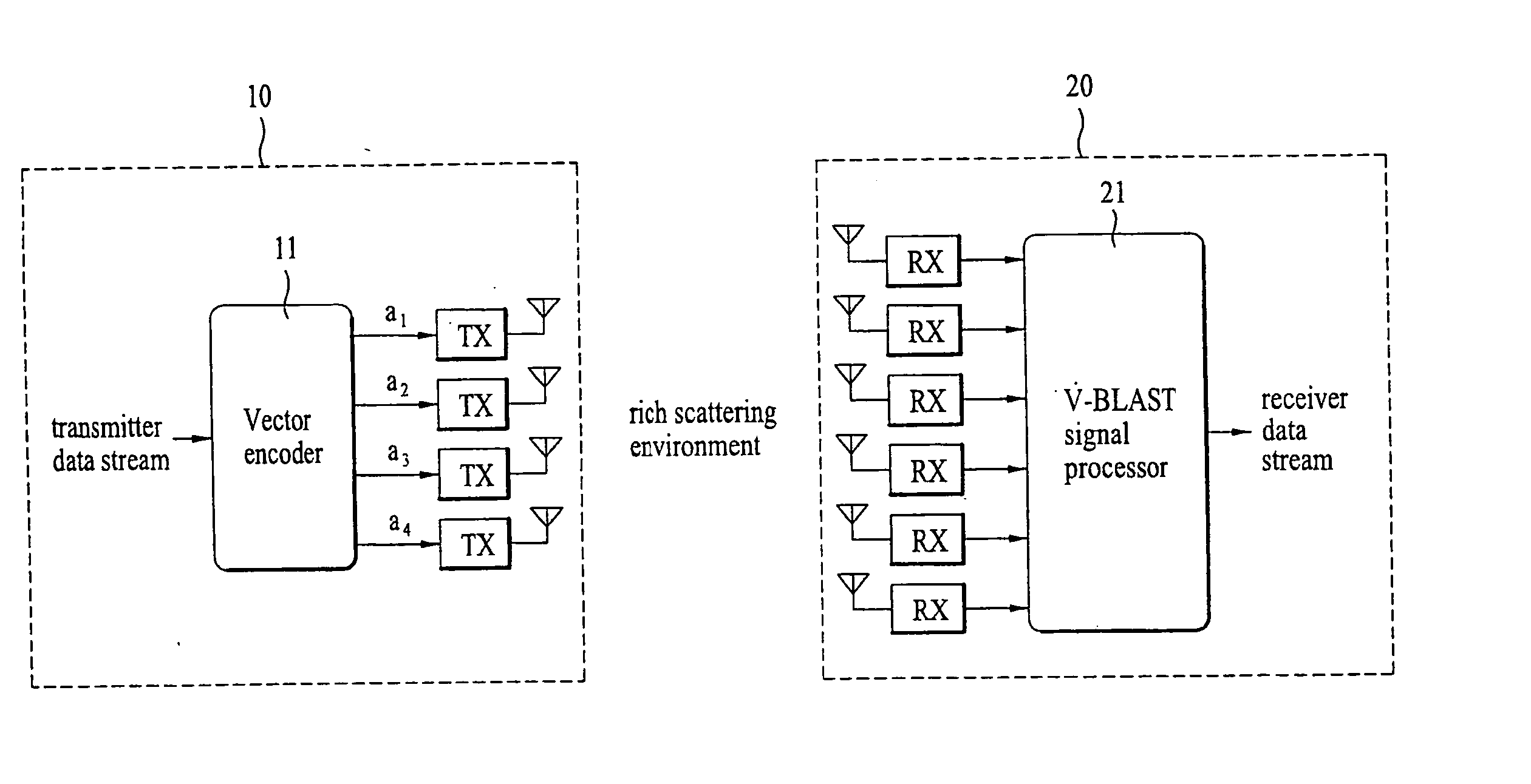
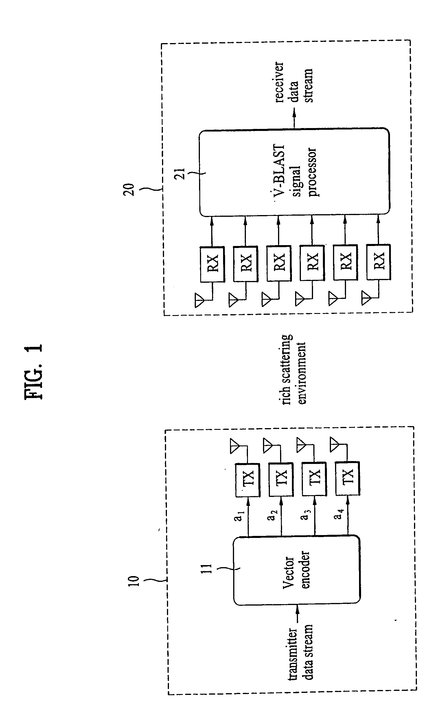
[0023] An example of a V-BLAST wireless system is schematically illustrated in FIG. 1, in which a single data stream is divided into multiple substreams for transmission in a rich scattering (multipath) environment. The V-BLAST system treats the multiplicity of scattering paths as separate parallel subchannels, each carrying a substream of data.

[0024] Referring to FIG. 1, the V-BLAST system includes a vector encoder 11 and a V-BLAST signal processor 21 at a receiver 20. The vector encoder 11, for example as part of a fixed host 10 (e.g., a base station or Node B) or a transmitting device, is connected in parallel to M antennas for respectively transmitting a plurality of data substreams a.sub.1-a.sub.4. The V-BLAST signal processor 21, as part of a subscriber unit, a mobile terminal, a mobile device or a user equipment (UE) 20, for example, (hereinafter, a mobile terminal) is connected in parallel to N antennas, each for receiving the plurality of transmitted data substreams. As sho...


PUM


Abstract

A method of mobile communication including a transmitter having multiple transmitters and a receiver having multiple receivers. The method includes adding a cyclic redundancy check (CRC) code to a data block to be transmitted and spatially segmenting the data block according to a modulation scheme and a coding rate of each respective transmit antenna of the multiple antennas.

Description

CROSS-REFERENCE TO A RELATED APPLICATION[0001] This application claims the benefit of Korean Application(s) No. 10-2003-0031026 filed on May 15, 2003, which is incorporated by reference.[0002] 1. Field of the Invention[0003] The present invention relates to wireless communication systems, and more particularly to a mobile communication system and signal processing method in which an indicator such as a cyclic redundancy check (CRC) code added to a data block is used to determine whether an error in transmission has occurred.[0004] 2. Background of the Invention[0005] Multiple-input multiple-output (MIMO) wireless communication systems use multiple-element antenna arrays to increase a user capacity in rich multipath environments by exploiting the spatial properties of the multipath channel. One such system is the vertical BLAST (Bell Laboratories Layered Space-Time) system, which uses a vertically layered space-time architecture as opposed to the diagonally layered space-time archite...

Claims


Application Information

Patent Timeline
IPC IPC(8): H04B7/04H03M13/09H04J99/00H04L1/00H04L1/06H04L1/08H04L1/16H04L1/18H04W16/28H04W28/00H04W28/04H04W28/18H04W88/02H04W92/10
CPCH04L1/0003H04L1/0009H04L1/0061H04L1/0068H04L1/0071H04L1/06H04L1/08H04L1/16H04L1/1812H04L2001/0098H04B7/04
Inventor KIM, BONG HOESEO, DONG YOUNSIM, DONG HIKOO, HYOUN HEE
Owner AEGIS 11 SA
Learn More