Fuel filter

a fuel filter and filter body technology, applied in the field of filters, can solve the problems of affecting the functioning of the filter, not being able to drain water from the unfiltered side as well as the clean side without dismantling the filter, etc., and achieve the effect of simple fuel filter design, and simple design of the filter

Inactive Publication Date: 2005-01-06
MANN HUMMEL GMBH
View PDF9 Cites 4 Cited by
  • Summary
  • Abstract
  • Description
  • Claims
  • Application Information

AI Technical Summary

Benefits of technology

[0007] Water can be drained out completely from both the unfiltered side and the clean side due to the fact that a device for separation and drainage of water is provided on both the unfiltered side and the clean side. This device makes is possible to drain off the water without having to dismantle the filter.
[0008] Each device advantageously has a collecting chamber comprising a closable outlet opening. The outlet opening is advantageously sealed by a gasket. A simple design is obtained when the seal is provided by a packing ring held by a water drain plug between two contact surfaces. The outlet opening is formed in particular on a water drain plug.
[0009] A simple design of the fuel filter is obtained when the water drain plug has a first channel arranged radially outside of the central axis of the water drain plug, opening into a first collecting chamber and a second channel situated coaxially with the central axis of the drain plug and opening into a second collecting chamber. The two devices, one on the unfiltered side and one on the clean side, are thus formed on a common water drain plug. The two devices can be actuated together, so this makes it simple to drain water from the unfiltered side and from the clean side at the same time. The second channel is advantageously closed by a gasket which is attached to the housing. When the water drain plug is unscrewed, the gasket remains stationary while the channel situated in the water drain plug is unscrewed. This makes it possible to open the channel by a simple method. The gasket is advantageously designed as a sealing ring held on a pin or plug, whereby the pin protrudes into the channel. However it may also be advantageous for the gasket to be attached to a plunger or push rod and to be pressed against an opening in the end of the channel by a spring. Manufacturing tolerances can be compensated by the spring, so that a good seal of the channel is always assured. The spring path is limited so that the channel is opened when the water drain plug is moved beyond a certain distance along its path of movement.
[0010] An outlet opening is advantageously connected to a pipe into which a water drain plug protrudes. In this case, the outlet opening is at the bottom of a pot or cylindrical vessel, with the collecting chamber being formed in the pot. The outlet opening is advantageously sealed by a flat gasket, which is held in a sealing seat by a spring. Providing the flat gasket at the bottom of the pot ensures that all the collected water will be completely drained out. At the same time, secure sealing during operation is assured due to the spring. This device advantageously has an actuator which acts against the spring force. Simple operability of the device is obtained when the actuator is designed as a push rod. Pushing on the push rod results in the flat gasket being loosened from the sealing seat, thus opening the outlet opening.
[0011] It may be advantageous for the fuel filter to have a plurality of filter elements which are arranged in succession along the flow path. To ensure functioning of such a filter during operation, a device for separating and draining off water is provided on the unfiltered side and on the clean side of at least two filter elements, in particular all filter elements. This prevents water from collecting in all areas of the housing of the fuel filter.

Problems solved by technology

The collected water may seriously impair the functioning of the filter.
With known filters, it is not possible to drain water from the unfiltered side as well as from the clean side without dismantling the filter.

Method used


Image

  • Fuel filter
  • Fuel filter
  • Fuel filter

Examples


Embodiment Construction

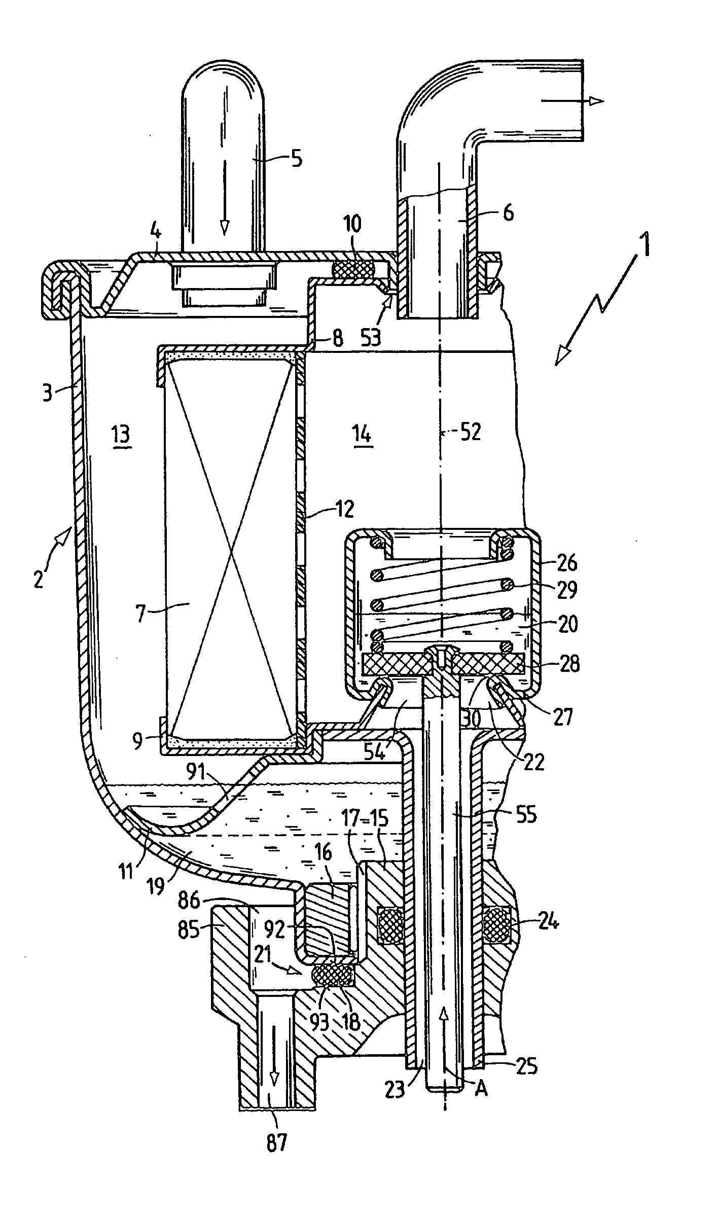
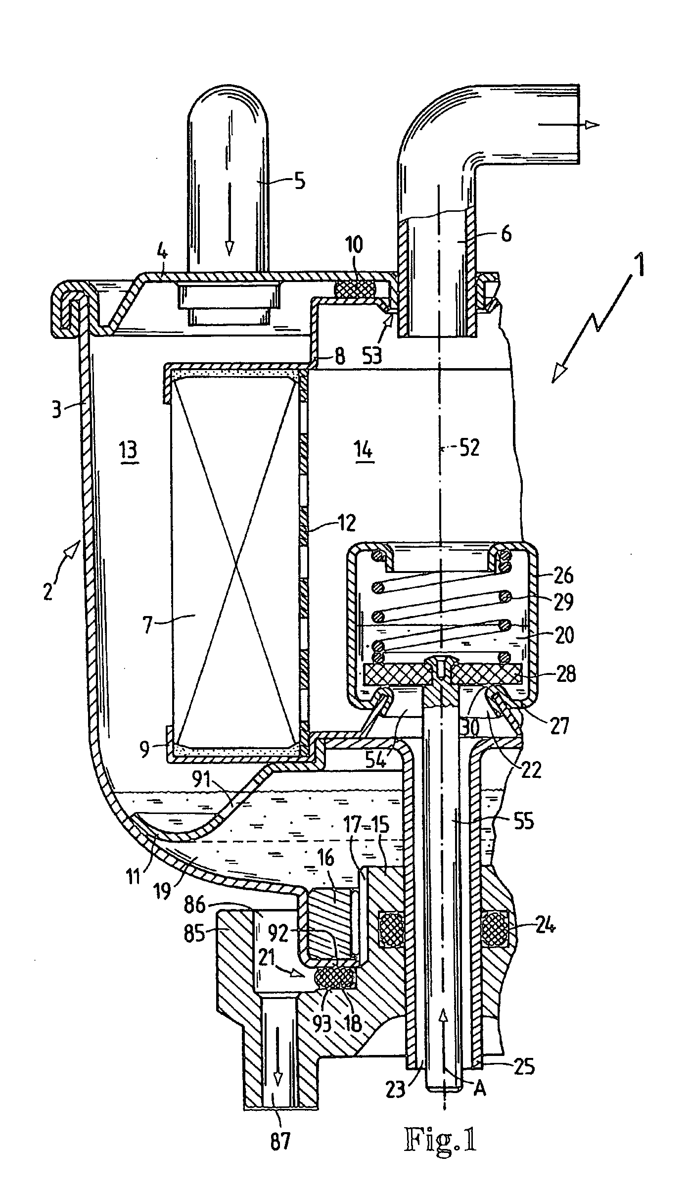
[0017]FIG. 1 shows a fuel filter 1 having a housing 2. The housing 2 comprises a housing pot 3 which is sealed with a cover 4. The fuel filter 1 has a symmetrical design, but only one side of the fuel filter 1 is shown in FIG. 1. A filter element 7 separating an unfiltered side 13 from a clean side 14 is provided in the housing 2. An inlet 5 in the cover 4 opens on the unfiltered side 13 radially outside of the longitudinal central axis 52 of the fuel filter 1. The outlet 6, which opens from the clean side 14, is secured in the cover so that it is coaxial with the longitudinal central axis 52. The end face of filter element 7 which faces the cover 4 is connected to a mounting member 8. The opposite end of filter element 7 is connected to a mounting member 9 and is sealed to make it fluid tight. The filter element 7 has a cylindrical construction and is made of filter paper pleated in lamellar folds. A central tube 12 is situated in the central channel of the filter element 7. The mo...


PUM

PropertyMeasurementUnit
forceaaaaaaaaaa
timeaaaaaaaaaa
distanceaaaaaaaaaa

Abstract

A fuel filter (1) having a housing (2) which has an inlet (5) on a unfiltered side (13) and an outlet (6) on a clean side (14). At least one filter element (7) is situated in the housing (2) in the flow path between the unfiltered side (13) and the clean side (14). To ensure the functioning of the filter and at the same time simplify the removal of collected water, a devices for separating and draining water are provided, respectively, on the unfiltered side (13) and on the clean side (14).

Description

BACKGROUND OF THE INVENTION [0001] This invention relates to a filter, and particularly to a fuel filter, comprising a housing with at least one filter element arranged therein so as to separate an unfiltered side from a clean side, and having an inlet opening into the unfiltered side and an outlet opening from the clean side, with the at least one filter element situated in a flow path between the inlet and the outlet. [0002] German Patent DE 42 39 099 C2 discloses a fuel filter having a housing in which a filter element is situated. A water collecting chamber is provided on the clean side of the filter element. A water drain plug for draining out the collected water protrudes into the water collecting chamber. [0003] When using certain filter materials, water may collect on both the unfiltered side of the filter element as well as on the clean side. The collected water may seriously impair the functioning of the filter. With known filters, it is not possible to drain water from th...

Claims


Application Information

Patent Timeline
Patent Type & Authority Applications(United States)
IPC IPC(8): B01D35/16B01D36/00F02M31/125F02M37/16F02M37/22
CPCB01D35/16B01D36/006F02M31/125Y02T10/126F02M37/221F02M2037/225F02M37/16F02M37/24F02M37/32F02M37/44Y02T10/12
Inventor JOKSCHAS, GUENTERREYINGER, JOCHEN
Owner MANN HUMMEL GMBH
Why Eureka
Try Eureka