
Oven conveyor alignment system apparatus and method

a conveyor belt and alignment system technology, applied in the field of commercial ovens, can solve the problems of conveyor belt drift out of alignment, conveyor belts that wander in the transverse direction, conveyor parts,

Active Publication Date: 2005-01-06
CASA HERRARA
View PDF15 Cites 44 Cited by
  • Summary
  • Abstract
  • Description
  • Claims
  • Application Information

AI Technical Summary

Benefits of technology

"The patent describes an oven conveyor alignment system that uses a terminal roller and a conveyor belt to align the conveyor belt with the oven's elongated axis. The system includes a camera that generates a digital image signal of the conveyor belt's position, and a control computer that adjusts the alignment based on the image signal. The system can automatically or manually align the conveyor belt, and the alignment can be adjusted based on misalignment detected by the control computer. The technical effect of the invention is to improve the accuracy and efficiency of oven conveyor alignment, which can save time and reduce energy consumption."

Problems solved by technology

Many factors such as uneven loading or misaligned components can cause conveyor belts to wander in a transverse direction relative to the center of a roller.
Particular to oven conveyors, uneven heat distribution is problematic to alignment of the belt.
That is, uneven expansion of the wire mesh belt caused by a temperature gradient will cause the belt to drift out of alignment.
An oven may contain several compartments with doors and opening a particular door will cause a heat imbalance to the belt.
Also, commercial ovens are typically partially exposed to the ambient environment surrounding the oven.
Changing air flow within the ambient environment can cause a heat sensitive belt to become misaligned.
The problems associated with continuous misalignment of an oven conveyor can be very significant.
First, the belt could severely damage the inside walls of the oven.
Second, replacement of prematurely worn or damaged belts is a relatively expensive procedure both in actual cost and opportunity cost.
The belts themselves are expensive at a cost of approximately $2,500.00 each.
The man hours required for replacement is an additional cost.
Furthermore, the entire oven must be shut down and cooled down, and therefore not producing volume during down time.
The mechanical switches, though, cannot continuously withstand the harsh environment inside an oven.
Also, mechanical alignment systems are not reliable by today's standards, since they can frequently drift out of calibration.
Thus, the mechanical alignment system will not be particularly suitable for making fine adjustments in alignment.

Method used


Image

  • Oven conveyor alignment system apparatus and method
  • Oven conveyor alignment system apparatus and method
  • Oven conveyor alignment system apparatus and method

Examples


Embodiment Construction

[0022] The following description is provided to enable any person skilled in the art to make and use the invention and sets forth the best modes contemplated by the inventor of carrying out his invention. Various modifications, however, will remain readily apparent to those skilled in the art, since the generic principles of the present invention have been defined herein specifically to commercial ovens.

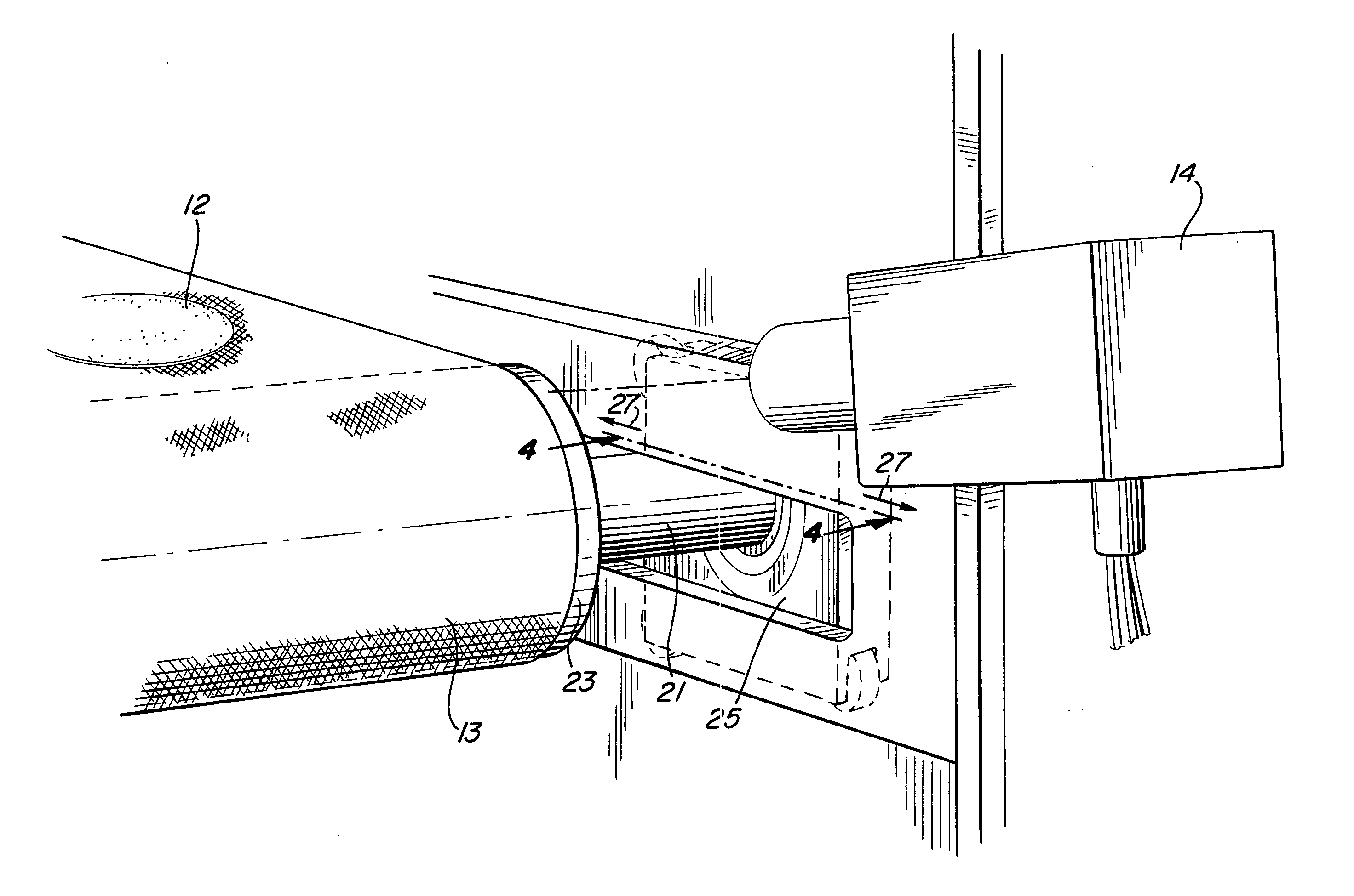
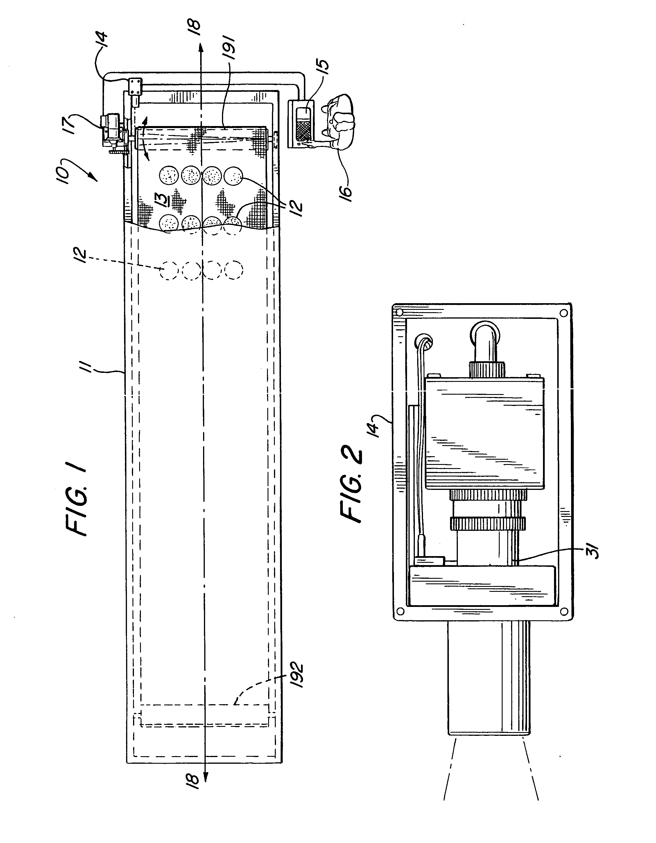
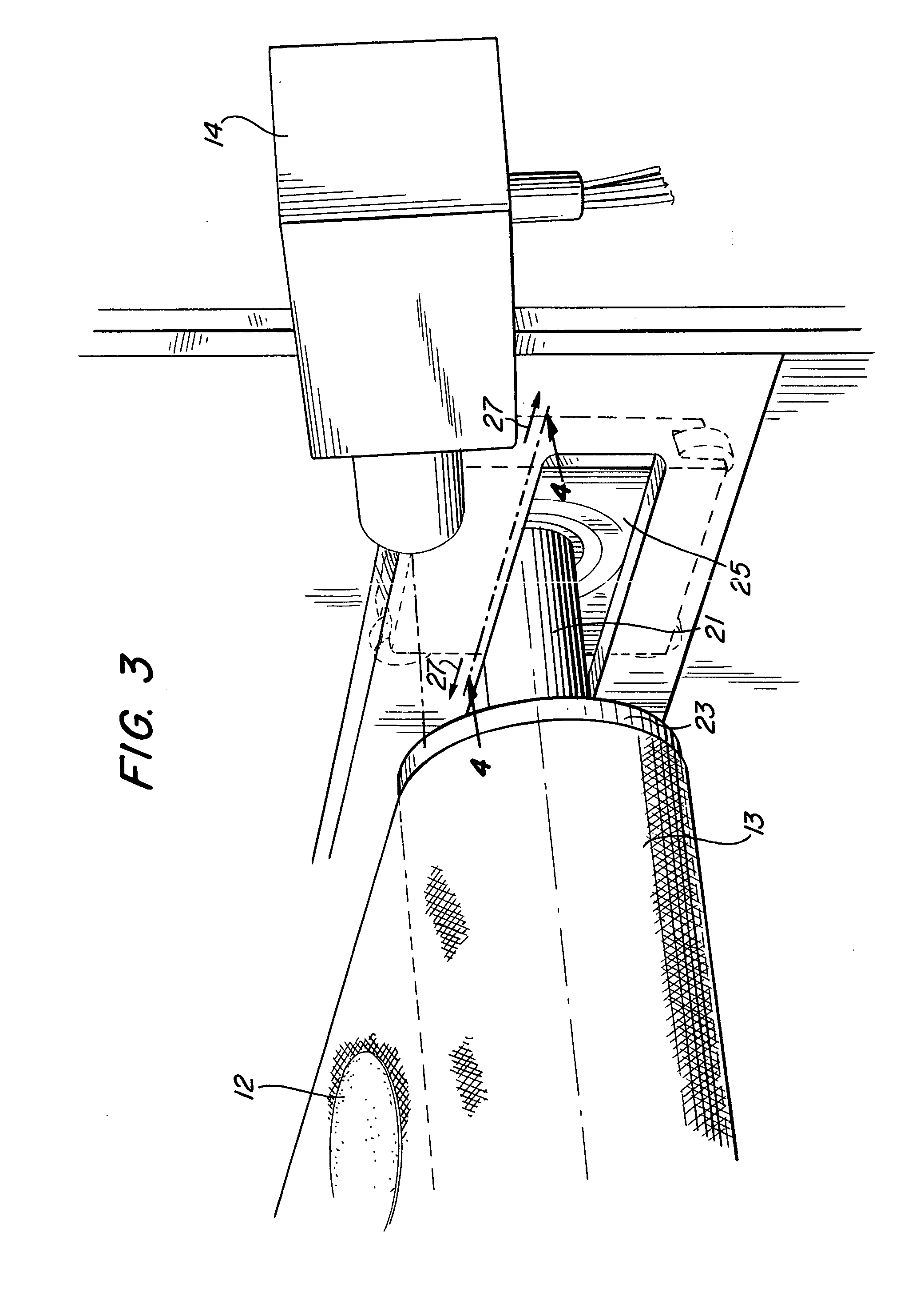
[0023] An oven conveyor alignment system for maintaining a conveyor belt centered on its supporting rollers is disclosed. A top view of the system 10 of the present invention is shown in FIG. 1. Oven 11 is generally an elongated rectangular shape and is symmetrical about axis 18. Conveyor belt 13 rotates in the oven about terminal rollers 191 and 192 (shown as dashed lines). Conveyor 13 communicates food items 12, such as tortillas, through the oven 11 along axis 18.

[0024] The purpose of the alignment system 10 of the invention is to keep conveyor 13 centered with respect to axis 1...


PUM


Abstract

An oven conveyor alignment system for maintaining a conveyor belt centered on its supporting rollers is disclosed. The system comprises a camera that generates an image of alignment and stores it as a digital pixel representation. Thus, the system is able to take advantage of new improvements in digital camera resolution. The image information is used by interactive software that is able to transmit an electrical signal to a tension adjustment assembly.

Description

BACKGROUND OF THE INVENTION [0001] 1. Field of the Invention [0002] This present invention pertains generally to commercial ovens. More particularly, the present invention relates to systems for maintaining alignment of conveyor belts. The present invention is particularly, but not exclusively, useful for maintaining alignment of an oven conveyer, evenly on its rollers. [0003] 2. Description of the Related Art [0004] Large commercial ovens used for baking food items, such as tortillas, typically employ conveyors to progress items within the oven during the baking process. A conveyor is typically comprised of an endless belt mounted on a series of rollers, with one roller driving the belt while the other rollers guide the belt and maintain its alignment. The tension in the belt must be maintained because the roller, which drives the conveyor, is usually friction driven; that is, the only force operating on the belt is the friction generated by the tension of the belt on the roller. T...

Claims


Application Information

Patent Timeline
Patent Type & Authority Applications(United States)
IPC IPC(8): B65G23/44B65G43/00
CPCB65G43/00B65G23/44
Inventor MEADE, RONALD
Owner CASA HERRARA
Learn More