Working machine

a technology of working machine and guard cover, which is applied in the direction of mechanical machines/dredgers, keyhole guards, transportation and packaging, etc., can solve the problems of large space required for opening and closing the cover, disadvantages of the related art working machine in the points of production steps, cost and appearance of the machine, etc., and achieve the effect of simplifying the structure of the locking mechanism of the guard cover

Inactive Publication Date: 2005-01-06
KOBELCO CONSTR MASCH CO LTD
View PDF5 Cites 10 Cited by
  • Summary
  • Abstract
  • Description
  • Claims
  • Application Information

AI Technical Summary

Benefits of technology

[0012] The object of the present invention is to provide a working machine, which can simplify a locking mechanism for a guard cover and in which the guard cover is difficult to be opened by unauthorized persons.
[0016] Thus the structure of the locking mechanism for the guard cover is simplified and the working machine of the present invention is advantageous in points of the production steps, cost of the machine, and for aesthetic purposes.
[0017] Further, the locking mechanism for the guard cover is a kind of key concealed within the window cover, and the guard cover is difficult to be opened by unauthorized persons. Thus, the possibility of operating inner apparatus without authorized persons' permission becomes low.

Problems solved by technology

In this case, the guard cover is large and heavy, its opening and closing are troublesome and further a space required for opening and closing the cover is large.
The working machine of the related art has been disadvantageous in the points of the production steps, cost and appearance of the machine.
Further, since the position of a locking mechanism of the guard cover and its open-close method can be seen from the outside easily by a key hole or the like, there was a problem that the possibility of breaking the locking by unauthorized persons is high.

Method used


Image

  • Working machine
  • Working machine
  • Working machine

Examples


Embodiment Construction

[0023] A working machine according to the present invention will be described with reference to embodiments shown in the drawings below.

[0024] In the following embodiments, a hydraulic excavator is illustrated as an application object.

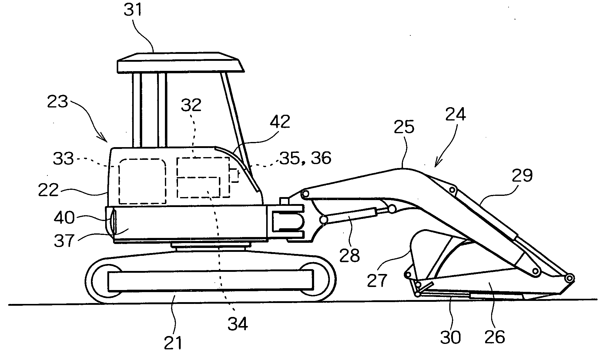
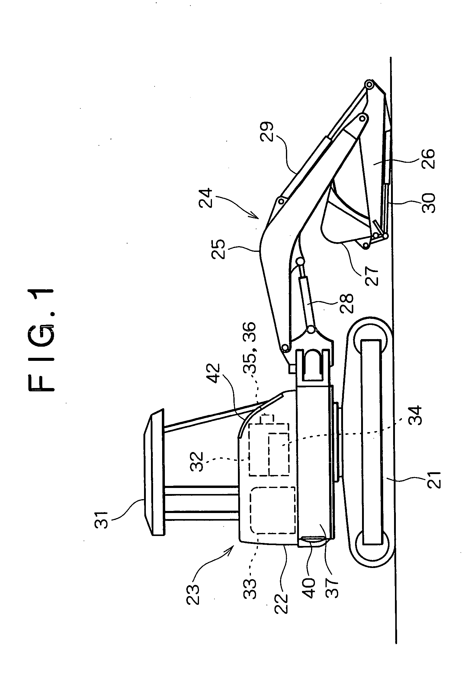
[0025] In this hydraulic excavator a base machine 23 is formed in such a manner that an upper rotating body 22 is rotatably mounted on a crawler type lower traveling body 21 around its vertical shaft, as shown in FIG. 1. Onto this base machine 23 are attached a working attachment 24 comprising a boom 25, an arm 26, a bucket 27, hydraulic cylinders 28, 29, 30 which operate them, and a swing cylinder (not shown), which swings the entire attachment in opposite directions.

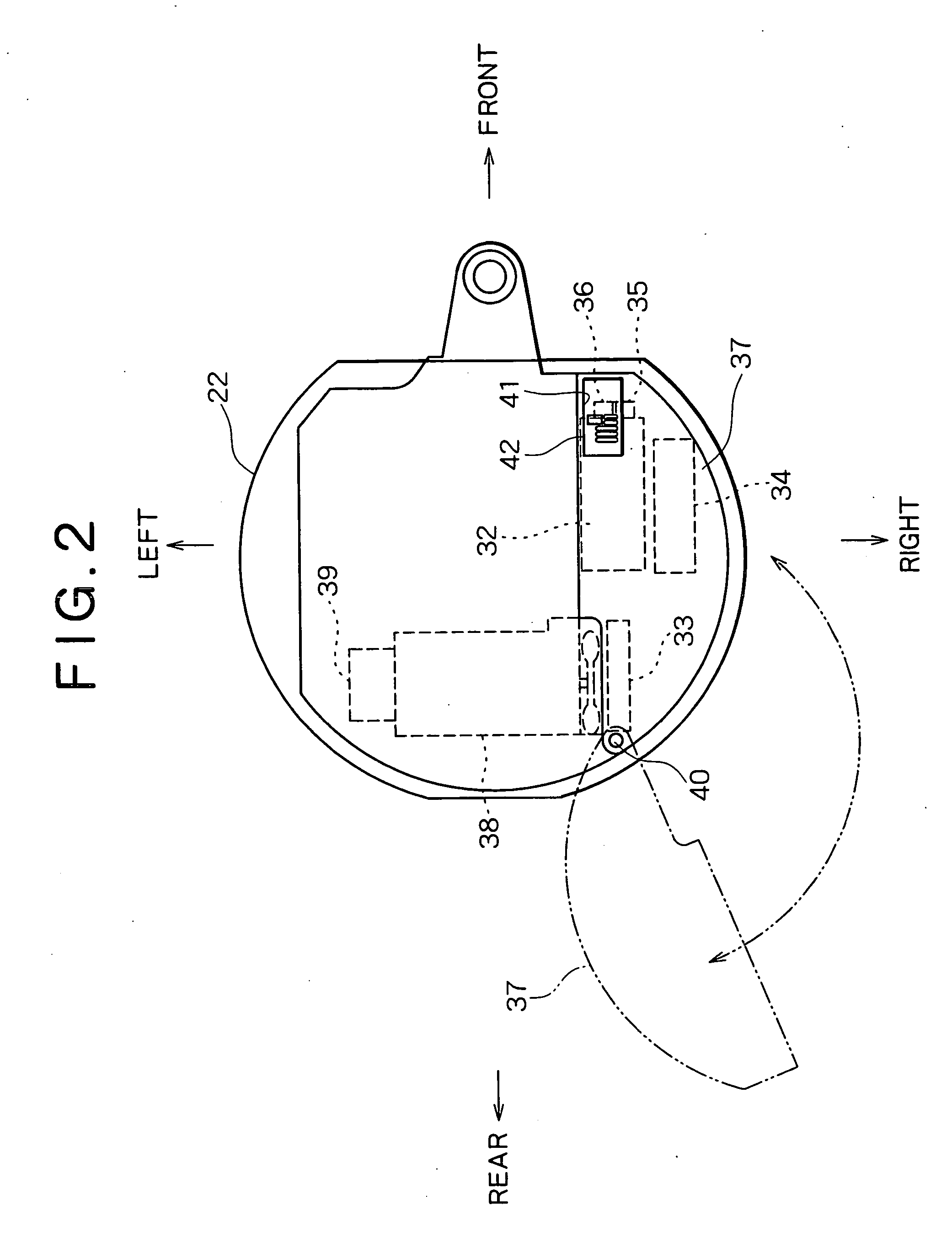
[0026] In this hydraulic excavator, as shown in FIGS. 1 and 2, the following apparatuses are disposed on an outer peripheral portion of the upper rotating body 22 (for example, a right side portion when an operator sitting on the operator's seat viewed. The example will be illustrated ...


PUM


Abstract

The present invention is a working machine in which apparatus disposed in an outer peripheral portion of the base machine is covered with a openable guard cover, a window for maintenance, which is opened and closed by a window cover, is provided in front surface of the guard cover, and a locking mechanism, which locks the guard cover in a closed mode and unlocks the guard cover by being operated from the outside, is provided in the inside of the window. According to the present invention, the locking mechanism for the guard cover can be simplified and the guard cover can be made hard to be opened by unauthorized persons.

Description

BACKGROUND OF THE INVENTION [0001] 1. Field of the Invention [0002] The present invention relates to a working machine such as a hydraulic excavator including a guard cover, which covers pieces of apparatus. [0003] 2. Description of the Related Art [0004] In an upper rotating body of a hydraulic excavator are disposed pieces of apparatus such as a working oil tank, a radiator, a main control valve, a multi control valve and a selector valve and the like. These are covered with a guard cover, and the maintenance of the apparatus or the like in the cover is performed by opening the cover. [0005] In this case, the guard cover is large and heavy, its opening and closing are troublesome and further a space required for opening and closing the cover is large. Thus, a technology that an openable small window is provided in the cover and the apparatus or the like, which require daily maintenance, are provided in the guard cover so as to face this small window, has been known (see Japanese P...

Claims


Application Information

Patent Timeline
Patent Type & Authority Applications(United States)
IPC IPC(8): E02F9/00B62D25/10E02F3/34E02F9/08E02F9/24
CPCB62D25/10E02F9/0891E02F3/325
Inventor IMASHIGE, HIROKAZU
Owner KOBELCO CONSTR MASCH CO LTD
Why Eureka
Try Eureka