Grill with independent heating zones

Active Publication Date: 2005-01-06
GARLAND COMML IND
View PDF6 Cites 72 Cited by
  • Summary
  • Abstract
  • Description
  • Claims
  • Application Information

AI Technical Summary

Benefits of technology

[0010] In a second embodiment of the present invention, the heater comprises a gas burner having a first group of ports disposed to provide the minimal heat and a second group of ports disposed to provide the maximal heat. In one aspect of this embodiment, the second group has more ports than the first group.
[0011] In a third embodiment of the present invention, the heater comprises a gas burner that has a surface in which

Problems solved by technology

The clamping system involves a substantial and often complex metal fabrication that adds cost

Method used


Image

  • Grill with independent heating zones
  • Grill with independent heating zones
  • Grill with independent heating zones

Examples


Embodiment Construction

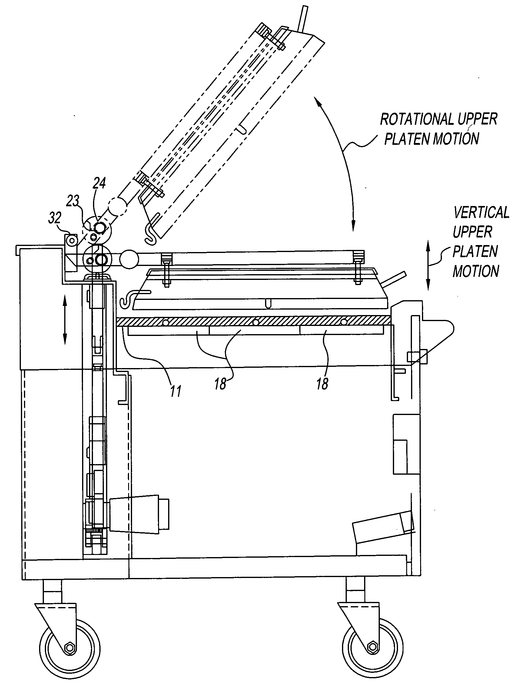
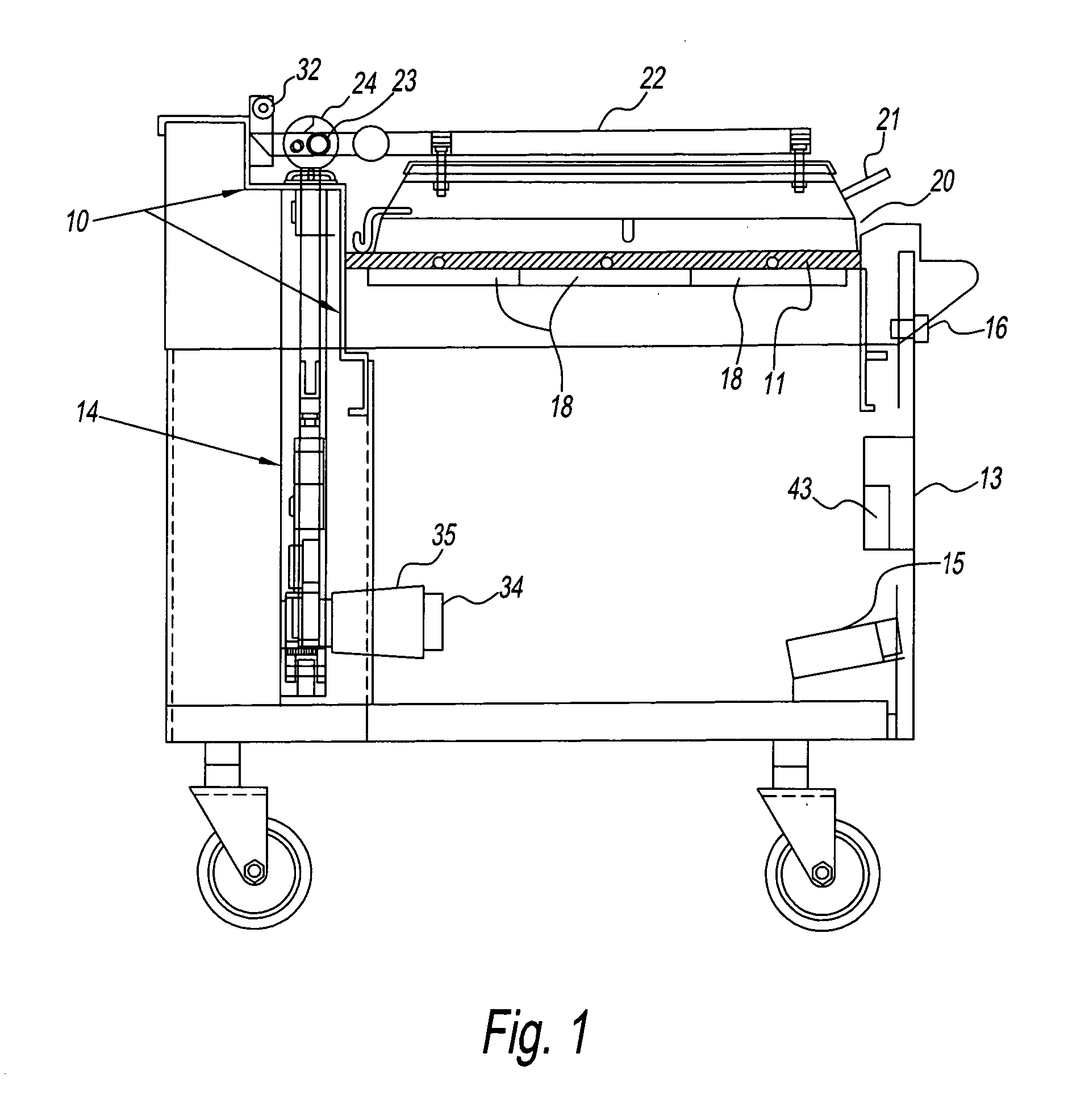
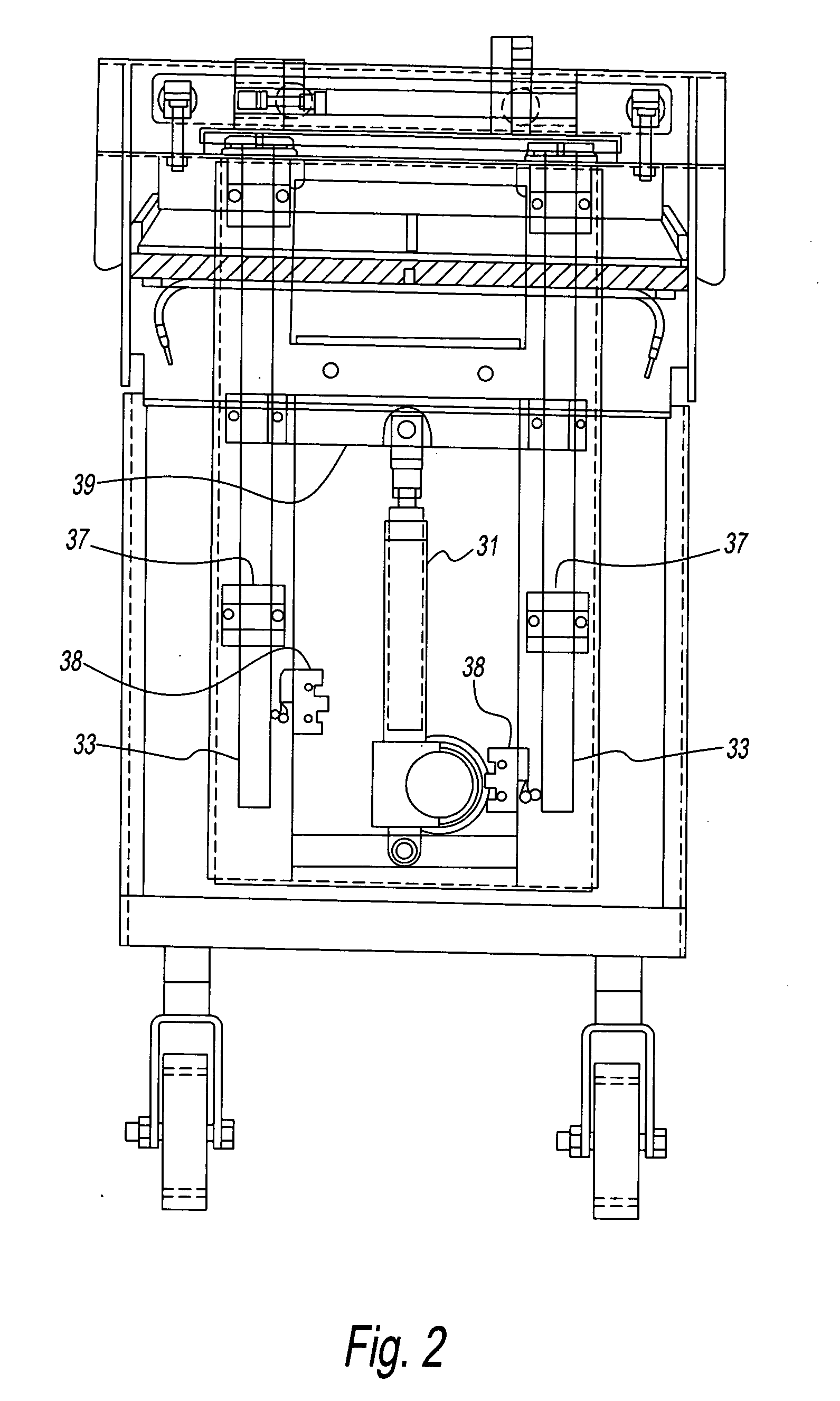
[0033] Referring to FIGS. 1-3, a preferred configuration of a clamshell grill embodiment of the present invention comprises a support structure 10 to which a lower cooking platen 11 is horizontally mounted. Lower platen 11 has a smooth level cooking surface on its upper side and corresponds to the griddle plate of the gas or electric griddle embodiments of FIG. 4 or 10. Lower platen 11 is heated to cooking temperature by a plurality of heating units 18, which may be gas or electric. By way of example, three heating units 18 are shown. In this embodiment, lower platen 11 is of substantial dimension, for example two feet by three feet, to accommodate large numbers of food items at once.

[0034] An upper platen assembly is movably mounted to the rear of support structure 10 by means of a positioning mechanism. The upper platen assembly comprises an upper cooking platen 20 heated to cooking temperature by heating elements mounted within a casing. Upper cooking platen 20 is either smaller...


PUM


Abstract

A grill having a platen with a plurality of heating zones. Each heating zone has a heating unit. Thermal transfer between adjacent heat zones is limited by air gaps and insulation. The heater unit of each zone has a heater that is disposed to attain substantially uniform temperature of the platen for that zone before a temperature sensor senses a set temperature during either pre-heat or recovery modes.

Description

[0001] This application claims priority of U.S. Provisional application No. 60 / 420,179, filed on Oct. 22, 2002, the entire contents of which are incorporated by reference.FIELD OF THE INVENTION [0002] This invention relates to a grill with a plurality of separately controlled heating zones and, also, to a clamshell grill in which the griddle is disposed. BACKGROUND OF THE INVENTION [0003] Conventional griddle plates or platens are made from steel or cast iron and are heated by tubular sheathed elements as, for example, disclosed in U.S. Pat. No. 3,843,315. The heating elements are maintained in contact with the underside of the griddle plate by a clamping system to maximize heat transfer and prevent overheating of the heating elements. The clamping system involves a substantial and often complex metal fabrication that adds cost and weight to the cooking appliance. The clamping system is secured to the griddle plate by a large number of studs that are screwed into holes or welded on ...

Claims


Application Information

Patent Timeline
IPC IPC(8): A47J27/62A47J37/06A47J37/07
CPCA47J27/62A47J37/067A47J37/0704F23D2900/14041F23D14/34F23D14/583F23D14/02
Inventor JONES, DOUGLAS J.NEVAREZ, ROBERTO
Owner GARLAND COMML IND
Why Eureka
Try Eureka