Image reading method, image reading apparatus, and image forming apparatus

Inactive Publication Date: 2005-01-06
KONICA MINOLTA BUSINESS TECH INC
View PDF5 Cites 15 Cited by
  • Summary
  • Abstract
  • Description
  • Claims
  • Application Information

AI Technical Summary

Benefits of technology

[0007] In view of the above problem, a first object of the present invention is to provide an image reading method for rea

Problems solved by technology

This leads to a problem that images obtained by color reading

Method used


Image

  • Image reading method, image reading apparatus, and image forming apparatus
  • Image reading method, image reading apparatus, and image forming apparatus
  • Image reading method, image reading apparatus, and image forming apparatus

Examples


Embodiment Construction

[0027] Hereinafter, description is given to an embodiment of an image reading apparatus according to the present invention, by way of an example of an image reader unit included in a digital color copier.

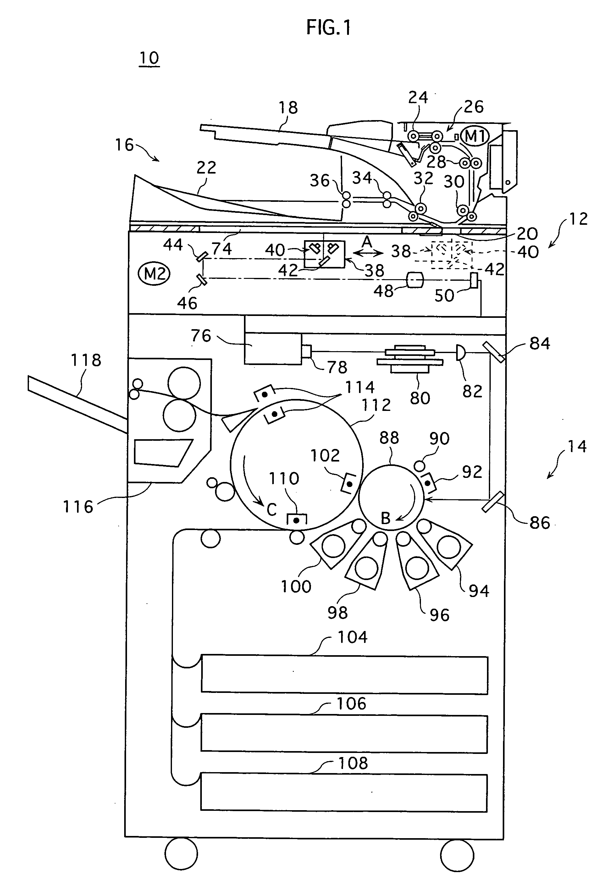
[0028]FIG. 1 is a schematic view illustrating a structure of a digital color copier (hereinafter, referred to simply as the “copier”) 10.

[0029] The copier 10 is composed roughly of an image reader unit 12 for reading a document image, and a printer unit 14 for reproducing the read image by printing the image on a recording sheet.

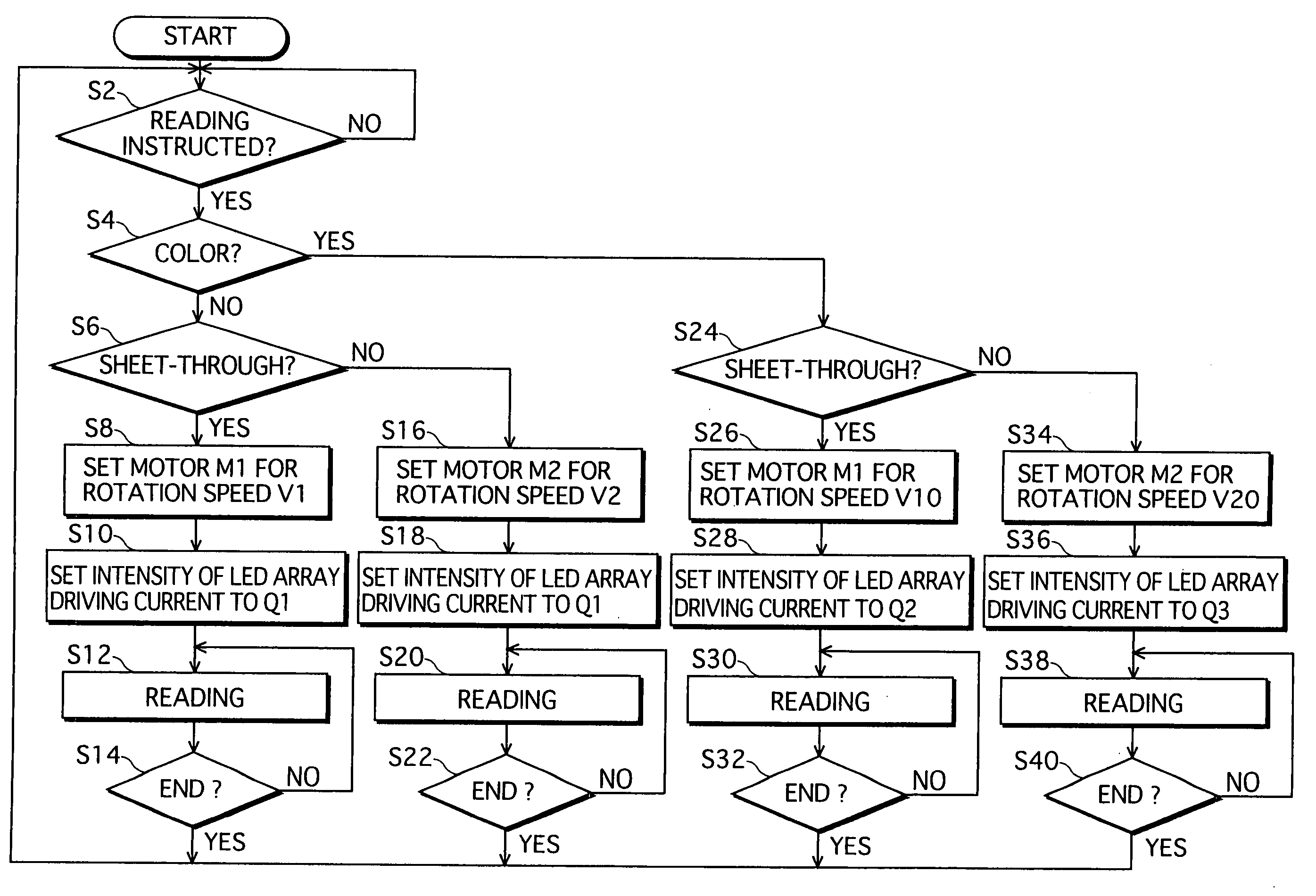
[0030] The image reader unit 12 is capable of reading a document image in sheet-through scheme, which falls in a category of fixed optical systems, as well as in a mirror-moving scheme, which falls in a category of moving optical systems. To be more specific, the sheet-through scheme is to read an image of a document by feeding the document past the optical system that stays (is fixed) in place. On the other hand, the mirror-moving scheme is to read an im...


PUM


Abstract

An image reading apparatus for reading an image of a document in a selected one of a first mode and a second mode includes: a light source adapted to illuminate a surface of the document; a CCD sensor adapted to receive light reflected from the document surface; and a light intensity controller adapted to control the light source to emit light at a different intensity between the first and second modes.

Description

[0001] This application is based on an application No. 2003-136460 filed in Japan, the contents of which are hereby incorporated by reference. BACKGROUND OF THE INVENTION [0002] (1) Field of the Invention [0003] The present invention generally relates to image reading technology, and more particularly to technology for reading a document image in a selected one of a plurality of different modes. [0004] (2) Description of the Related Art [0005] Conventionally, copiers capable of two different reading operations are commercially available for office use, for example. One of the modes is to read a document to obtain a color image and the other to obtain a monochrome image. Such copiers generally include a halogen lamp or a fluorescent lamp as a light source for illuminating a document surface. Light reflected from the document surface is received with a CCD sensor, thereby reading an image of the document. The CCD sensor may be a 4-line CCD sensor that is composed of a 1-line CCD senso...

Claims


Application Information

Patent Timeline
IPC IPC(8): G03B27/54G06T1/00G03B27/50H04N1/04H04N1/10H04N1/107H04N1/12H04N1/193H04N1/40H04N1/46
CPCH04N1/0282H04N1/02895H04N1/04H04N1/40056H04N1/1013H04N1/12H04N1/193H04N1/0446
Inventor IGUCHI, YUKINOBU
Owner KONICA MINOLTA BUSINESS TECH INC
Why Eureka
Try Eureka