Thermostat valve

A temperature-controlled valve and valve body technology, applied in balance valves, valve devices, valve details, etc., can solve the problems of piston shaft support ring 11b damage, large coolant flow resistance, and difficulty in ensuring quality uniformity, etc., to achieve production and assembly Ease, low part count, equal quality results

Active Publication Date: 2012-09-19
KOREA ELECTRONICS CO LTD
View PDF7 Cites 3 Cited by
  • Summary
  • Abstract
  • Description
  • Claims
  • Application Information

AI Technical Summary

Problems solved by technology

[0010] But, because this existing temperature control valve 1 comprises first spring 14 and second spring 16, first spring supporting part 15 and second spring supporting part 17, connecting part 18, valve plate 19, base part 13, There are many parts such as the fixed seat 3, so the number of parts is large, which leads to the problems of difficult manufacturing, complicated assembly process and high production cost
And, because many parts need to be manufactured or assembled in different processes from each other, it is difficult to ensure uniform quality
[0011] In addition, the temperature control valve 1 rotates the opening and closing member 12 due to the severe turbulent flow of the coolant flowing inside, and this rotation may cause damage to the piston shaft 11a or the support ring 11b, which may cause failure.
[0012] And, with respect to this temperature control valve 1, because the many parts that are positioned at its internal flow path, there is the problem that the flow resistance of cooling liquid is big.
And, when the engine is in overload operation, since the piston shaft 11a needs to overcome the first spring 14 and the second spring 16 simultaneously and elongate, the rigidity of the temperature detection movable part 11 also needs to be increased accordingly, which makes it difficult to adjust the temperature. Miniaturization of the detection movable part 11 and its surrounding components

Method used


Image

  • Thermostat valve
  • Thermostat valve
  • Thermostat valve

Examples


Embodiment Construction

[0038] Hereinafter, preferred embodiments of the present invention will be described in detail with reference to the drawings.

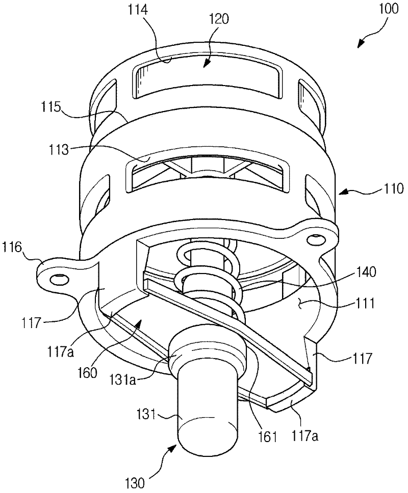
[0039] Such as Figure 4 As shown, the temperature control valve 100 provided by the present invention is arranged in the coolant flow path of a ship or a large industrial engine. The temperature control valve 100 plays the role of changing the flow path according to the temperature of the coolant flowing through the engine, so as to send the coolant to the flow path 31 connected to the water pump or the flow path 32 connected to the radiator. Here, although the case where the temperature control valve 100 is used in the coolant flow path of the engine is described as a preferable example, the application of the temperature control valve 100 of the present invention is not limited thereto, and it can also be applied to the temperature control valve 100 according to the temperature change of the fluid. Various industrial equipment or devices that need ...


PUM


Abstract

A thermostat valve is provided. The thermostat valve comprises a cylindrical valve, a cylindrical opening and closing member, a temperature sensing and operating unit, and a spring. One end of the valve is closed. An opened inlet port is formed in the opposite end of the valve. The first and second outlets of the valve housing are formed on the circumference at interval in a longitudinal direction. The cylindrical opening and closing member advances and retreats within the valve in order to selectively open and close the first and second outlets. The temperature sensing and operating unit has a body part and a piston shaft, the piston shaft is disposed at the main body portion and with the end portion protruding toward the external side of the main body portion being supported by the closed end portion of the valve. The spring is supported in a spring support member in order to press the opening and closing member. One end of the spring support member is supported in the opening and closing member, and the other end is installed in the inlet port of the valve housing.

Description

technical field [0001] The invention relates to a temperature control valve which selectively opens and closes the flow path according to the temperature change of the cooling liquid to automatically change the circulation path of the cooling liquid. Background technique [0002] The temperature control valve used in the engine cooling system can automatically change the circulation path of the coolant according to the temperature of the circulating coolant to keep the engine at an appropriate temperature. When the temperature of the coolant circulating in the early stage of engine operation is low, the coolant is supplied to the water pump by changing the flow path, so that the coolant is circulated to the engine again without passing through the radiator, thereby rapidly increasing the engine temperature. When the temperature of the coolant rises above a certain level due to the operation of the engine, the coolant is supplied to the radiator side by changing the flow path...

Claims


Application Information

Patent Timeline
Patent Type & Authority Applications(China)
IPC IPC(8): F16K17/36F16K31/64F16K27/00
CPCF01P7/16F01P2007/146F01P2050/22F16K17/38F16K35/02
Inventor 朴熙完
Owner KOREA ELECTRONICS CO LTD
Why Eureka
Try Eureka