Systems and methods for performing protocol conversions in a work machine

a work machine and protocol technology, applied in the field of network interface systems, can solve problems such as the difficulty of communicating information from various protocols (e.g., rs-485, modbus) and become especially acu

Inactive Publication Date: 2005-01-06
CATERPILLAR INC
View PDF98 Cites 291 Cited by
  • Summary
  • Abstract
  • Description
  • Claims
  • Application Information

AI Technical Summary

Benefits of technology

[0011] Consistent with embodiments of the present invention, methods and systems may be provided for performing protocol conversions in an environment including a work machine...

Problems solved by technology

Problems arise, however, when modules connected to different types of data links need to communicate.
These problems become especially acute as the number of data links and protocols on a given work machine increases.
For example, communicating information from various protocols (e.g., J1939, RS232, RP1210, RS-422, RS-485, MODBUS, CAN, IS011783, ATA, etc.) over a TCP/IP-based network may be problematical in current work machine environments.
In addition, communicating information from multiple and different data links over a single data link protocol may pose particular difficulties.
Similarly, difficulties may be presented when modules connected to multiple and different data links simultaneously require information from a single disparate physical layer.
Further, problems arise when legacy systems need to communicate with other, perhaps newer, systems that are not compatible with the legacy protocols.
In certain instances, an inability to translate and communicate among and between protocols may impose significant limitations on the design and configuration of work machines and modules.
For example, the placement of modules within a given work machine or environment may be limited to the range of a particular protocol.
Maritime-specific modules,...

Method used


Image

  • Systems and methods for performing protocol conversions in a work machine
  • Systems and methods for performing protocol conversions in a work machine
  • Systems and methods for performing protocol conversions in a work machine

Examples


Embodiment Construction

[0027] Reference will now be made in detail to the exemplary aspects of the invention, examples of which are illustrated in the accompanying drawings. Wherever possible, the same reference numbers will be used throughout the drawings to refer to the same or like parts.

[0028] Overview

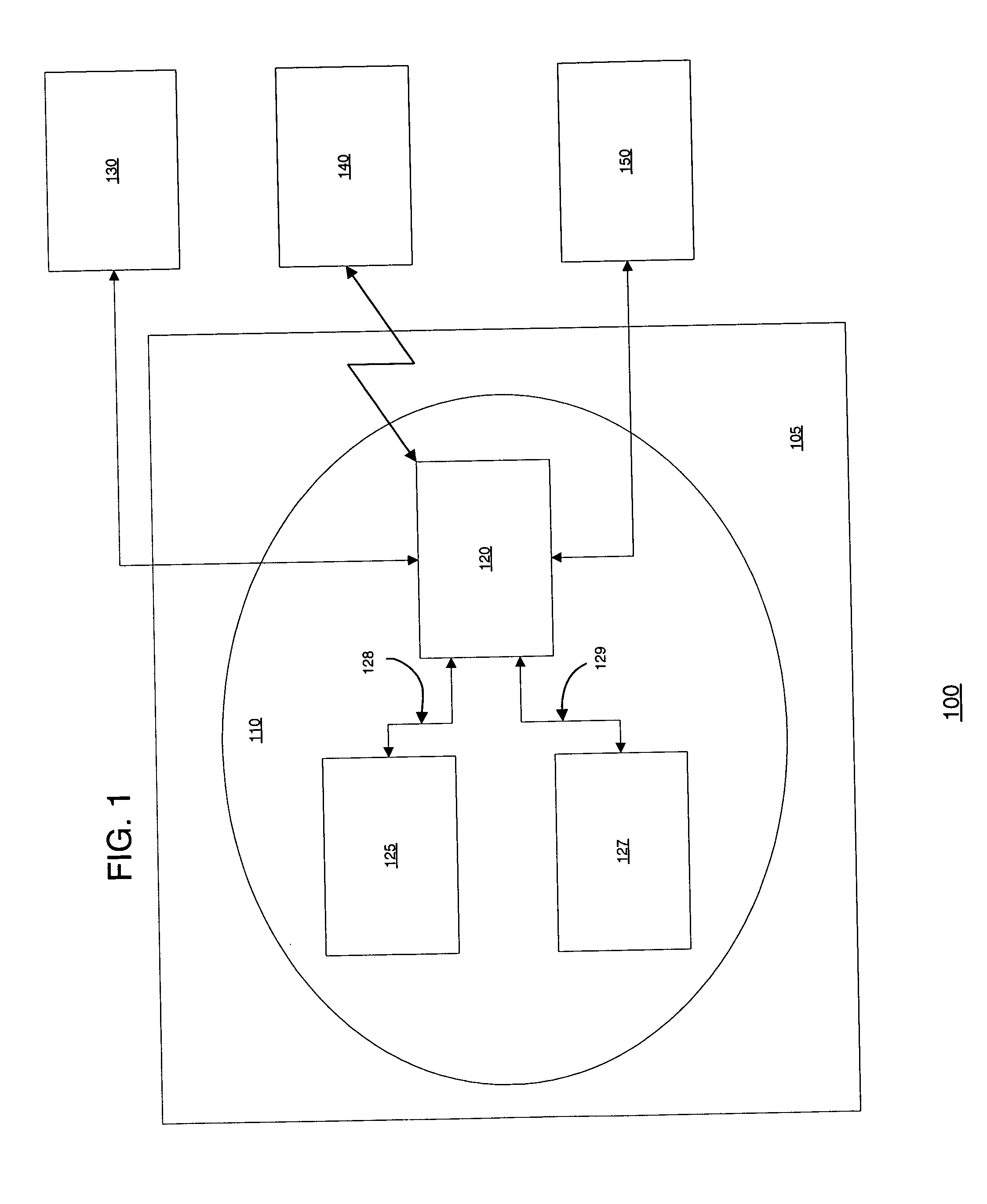
[0029]FIG. 1 illustrates an exemplary system 100 in which features and principles consistent with an embodiment of the present invention may be implemented. As shown in FIG. 1, system 100 may include a work machine 105 including an on-board system 110 comprising a gateway 120 and on-board modules 125, 127. System 100 may also include one or more off-board systems 130-150. Although gateway 120 is shown as a separate element, methods and systems consistent with the present invention may allow gateway 120 to be included in one or more elements, such as on-board modules 125 and / or 127.

[0030] A work machine, as used herein, refers to a fixed or mobile machine that performs some type of operation associated...


PUM


Abstract

Methods and systems are provided for performing protocol conversions in an environment including a work machine having one or more modules coupled to one or more data links. Such methods and systems may leverage one or more gateways to perform tunneling, translating, and bridging operations. Tunneling processes may include receiving a message from a source module in a first protocol, encapsulating the message within transmission units of a second protocol, and transmitting the encapsulated message via the second protocol. Translating processes may include receiving, by the gateway, a message in a first data link protocol including a parameter identifier. The gateway may match the parameter identifier with a parameter identifier included in a translation table and scale associated parameter data using a scale factor corresponding to a second data link protocol. The gateway may then provide the scaled parameter data to a module using the second data link protocol.

Description

CROSS REFERENCE TO RELATED APPLICATIONS [0001] This application claims the benefit of U.S. Provisional Application Ser. No. 60 / 483,915 entitled “Systems and Methods for Interfacing Off-Board and On-Board Networks in a Work Machine,” filed Jul. 2, 2003, owned by the assignee of this application and expressly incorporated herein by reference in its entirety. [0002] This application is related to U.S. application Ser. No. ______, entitled “SYSTEMS AND METHODS FOR PROVIDING SERVER OPERATIONS IN A WORK MACHINE,” filed Aug. 25, 2003, U.S. application Ser. No. ______, entitled “SYSTEMS AND METHODS FOR PROVIDING SECURITY OPERATIONS IN A WORK MACHINE,” filed Aug. 25, 2003, U.S. application Ser. No. ______, entitled “SYSTEMS AND METHODS FOR PROVIDING NETWORK COMMUNICATIONS BETWEEN WORK MACHINES,” filed Aug. 25, 2003, and U.S. application Ser. No. ______, entitled “METHODS AND SYSTEMS FOR PROVIDING PROXY CONTROL FUNCTIONS IN A WORK MACHINE,” filed Aug. 25, 2003, each owned by the assignee of t...

Claims


Application Information

Patent Timeline
IPC IPC(8): H04L29/06
CPCH04L69/08
Inventor KELLY, THOMAS J.WOOD, DANIEL C.FERGUSON, ALAN L.BIERDEMAN, PAUL W.JENKINS, BRIAN L.MEISS, TRENT R.SWANSON, ANDREW J.
Owner CATERPILLAR INC
Why Eureka
Try Eureka