
Disk array apparatus for and method of expanding storage capacity dynamically

a dynamic expansion and storage capacity technology, applied in the direction of memory address/allocation/relocation, instruments, input/output to record carriers, etc., can solve the problems of increasing the time required for first storage capacity expansion, reducing sequential access performance, and ineffectiveness of all data blocks, so as to shorten the time required, and expand the storage capacity of the disk array

Inactive Publication Date: 2005-05-31
KK TOSHIBA
View PDF12 Cites 85 Cited by
  • Summary
  • Abstract
  • Description
  • Claims
  • Application Information

AI Technical Summary

Benefits of technology

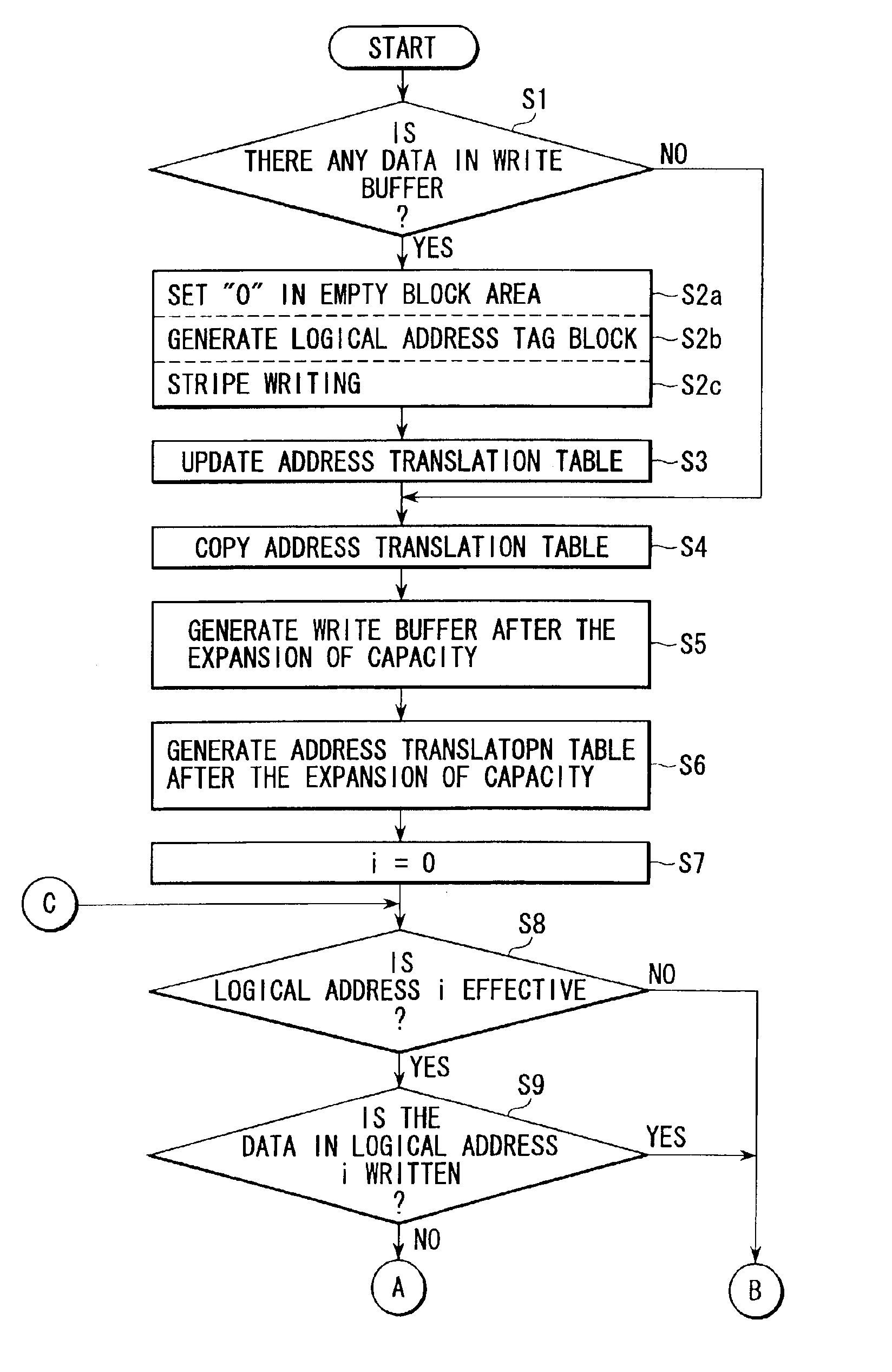
[0009]It is accordingly an object of the present invention to provide a disk array apparatus for and a method of expanding storage capacity dynamically which need not move the data corresponding to at least ineffective logical addresses to expand the storage capacity of the disk array by adding a disk drive, thereby shortening the time required to expand the storage capacity.

Problems solved by technology

In the first storage capacity expanding technique, however, it is necessary to write “0” into all of the data areas of the added disk drives, that is, to make all of the data blocks ineffective.
Consequently, the first storage capacity expanding technique requires a lot of time, depending on the storage capacity of the added disk drives.
Moreover, the first storage capacity expanding technique has another problem: since the mapping relationship between the logical addresses and the physical addresses after the expansion of the storage capacity is not optimized, the performance of sequential access decreases.
Therefore, in the second storage capacity expanding technique, the following problem arises: the relocation of data causes inputs to and outputs from the disk drives to take place, which degrades the performance of the input and output to and from the disk array apparatus after the expansion of the storage capacity.

Method used


Image

  • Disk array apparatus for and method of expanding storage capacity dynamically
  • Disk array apparatus for and method of expanding storage capacity dynamically
  • Disk array apparatus for and method of expanding storage capacity dynamically

Examples


Embodiment Construction

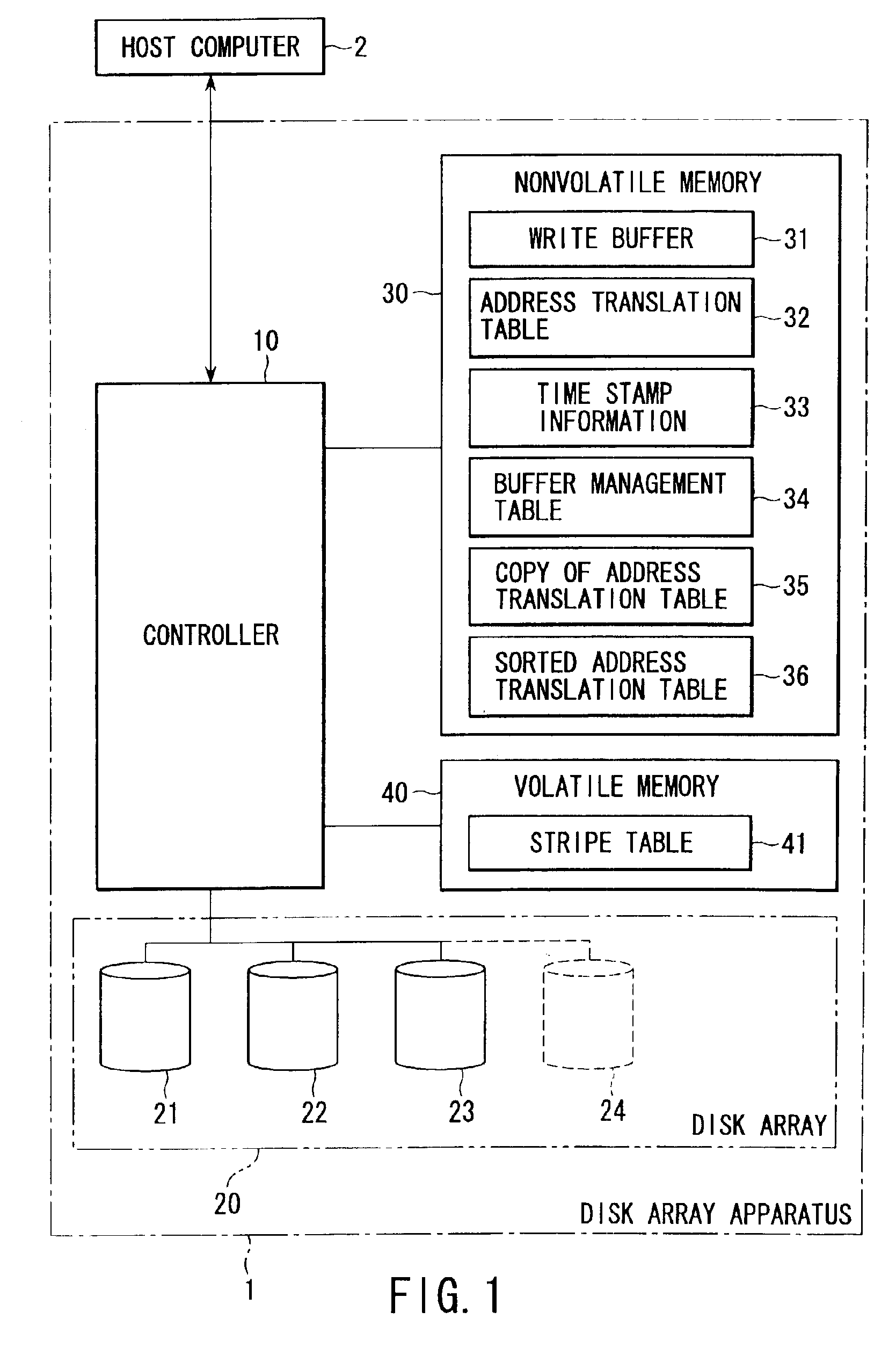
[0028]Hereinafter, referring to the accompanying drawings, an embodiment of the present invention will be explained. FIG. 1 is a block diagram showing the configuration of a computer system including a disk array apparatus 1 to which a log structured file system according to an embodiment of the present invention is applied. The computer system of FIG. 1 comprises a disk array apparatus 1 and a host computer 2 using the disk array apparatus 1. The disk array apparatus 1 comprises a controller 10, a disk array 20, a nonvolatile memory 30, and a volatile memory 40. The disk array 20, nonvolatile memory 30, and volatile memory 40 are each connected to the controller 10.

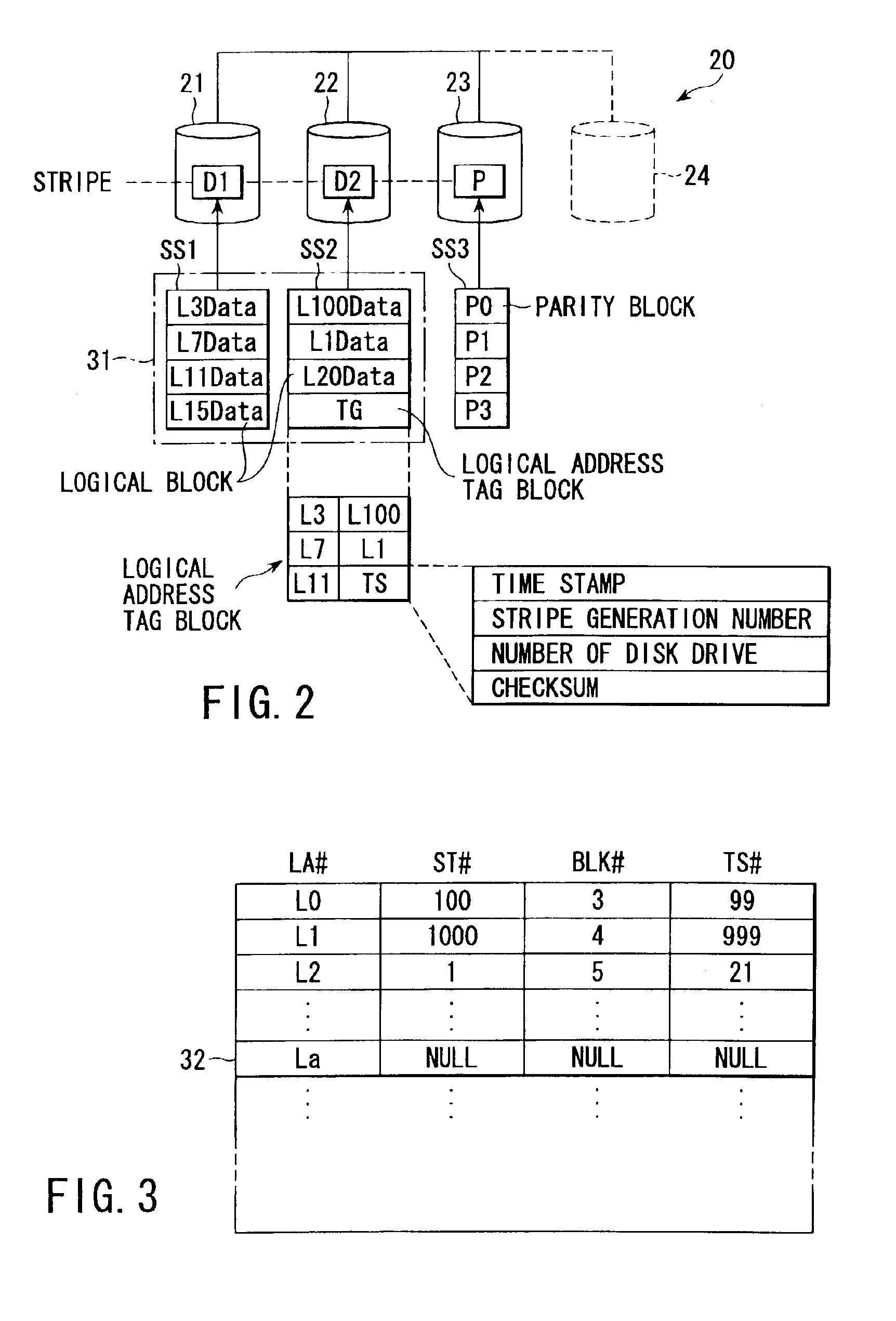
[0029]The disk array 20 is composed of a plurality of disk drives, for example, three disk drives 21, 22, 23. The disk array 20 has a redundant disk configuration so that, even if any one of the disk drives 21, 22, 23 fails, the data in the troubled disk drive can be regenerated (or recovered). To simplify the explanatio...


PUM


Abstract

A controller retrieves effective logical addresses sequentially according to a copy of an address translation table at the time of the start of storage capacity expansion in the process of expanding the storage capacity of a disk array by adding a disk drive to the disk array. The controller stores the data in the logical address into a restructured write buffer each time an effective logical address is retrieved. The controller writes one stripe worth of data blocks including one stripe of logical blocks and a logical address tag block into an empty area different from the area in which the data to be updated has been stored in the data array each time one stripe worth of logical blocks of data is accumulated in the write buffer.

Description

CROSS-REFERENCE TO RELATED APPLICATIONS[0001]This application is based upon and claims the benefit of priority from the prior Japanese Patent Application No. 2002-023919, filed Jan. 31, 2002, the entire contents of which are incorporated herein by reference.BACKGROUND OF THE INVENTION[0002]1. Field of the Invention[0003]This invention relates to a disk array apparatus with a disk array composed of a plurality of disk drives, and more particularly to a disk array apparatus for and a method of expanding storage capacity dynamically which are suitable in expanding the storage capacity of a disk array by adding disk drives.[0004]2. Description of the Related Art[0005]One known disk storage management method is called a Log Structured File System. The log structured file system has been described in detail in, for example, the following reference: “The Design and Implementation of a Log-Structured File System,” Mendel Rosenblum and John K. Ousterhout, ACM Transaction on Computer systems,...

Claims


Application Information

Patent Timeline
IPC IPC(8): G06F12/02G06F12/00G06F3/06
CPCG06F3/0608G06F11/1096G06F3/0689G06F3/0661
Inventor TOMITA, HARUO
Owner KK TOSHIBA
Learn More