Method and apparatus for placing sensors using 3D models

Inactive Publication Date: 2005-01-06
L 3 COMM CORP
View PDF15 Cites 91 Cited by
  • Summary
  • Abstract
  • Description
  • Claims
  • Application Information

AI Technical Summary

Benefits of technology

[0010] In one embodiment, the present invention discloses a method and apparatus for modeling placement of sensors using a 3D model. This novel system is for displaying and interactively modifying the location, orientation, field of view, and other parameters of one or more sensors, e.g., infrared sensors, ultrasonic sensors, motion sensors, and cameras, using a 3D model of the scene. This uniqu

Problems solved by technology

One problem with this approach is that the 2D model does not accurately capture the complex 3D projection of the scene into the 2D imager.
This significantly changes the area of coverage, and makes it difficult to guarantee that an area of ground will in fact be covered when the cameras are actually installed.
Another problem associated with this approach is that regions of occlusion are typically missed, resulting in unexpected blind-spots in camera coverage that are only apparent when the cameras are installe

Method used


Image

  • Method and apparatus for placing sensors using 3D models
  • Method and apparatus for placing sensors using 3D models
  • Method and apparatus for placing sensors using 3D models

Examples


Embodiment Construction

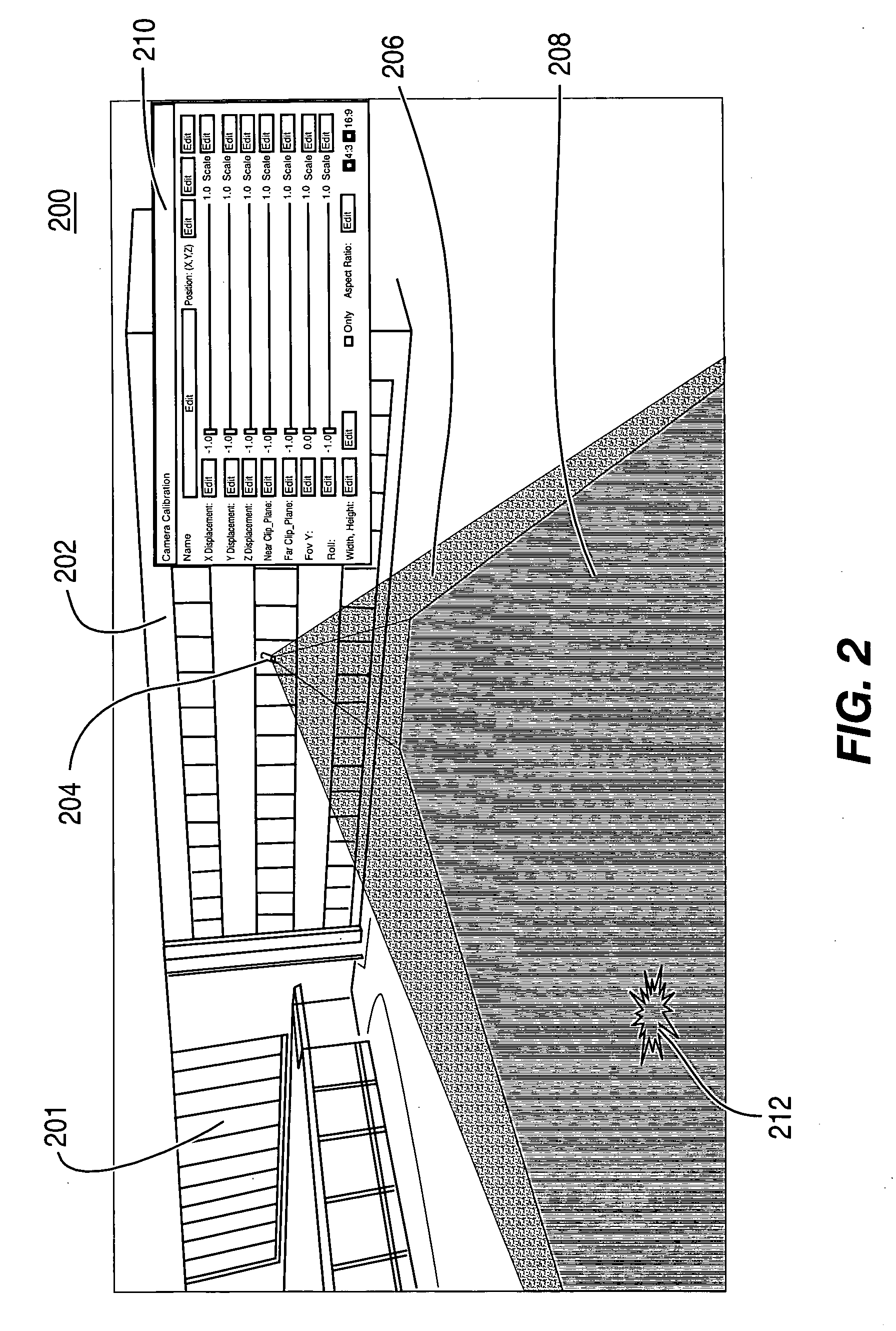
[0021] The present invention is a method and apparatus for sensor placement which displays and interactively modifies the location, orientation, field of view, and other parameters of one or more sensors, e.g., cameras, infrared sensors, ultrasonic sensors, and motion sensors, using a 3D model of the scene. In addition, the method and apparatus interactively display regions of occlusion, size of objects in the field of view, the image captured from the camera sensor, regions that are within the range of alarms (video-based or otherwise), and other image parameters in order to optimize the design of a sensor layout at a scene.

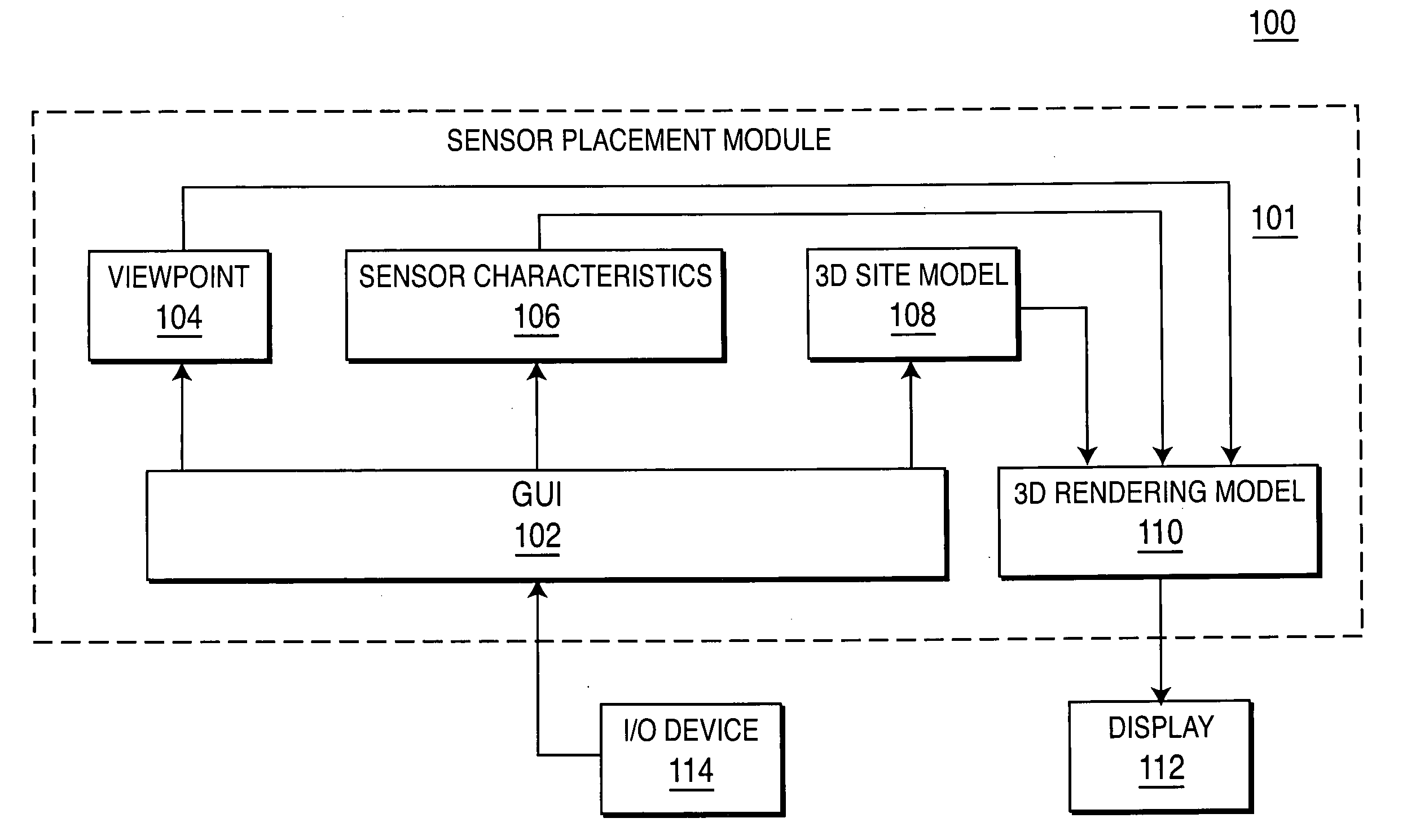
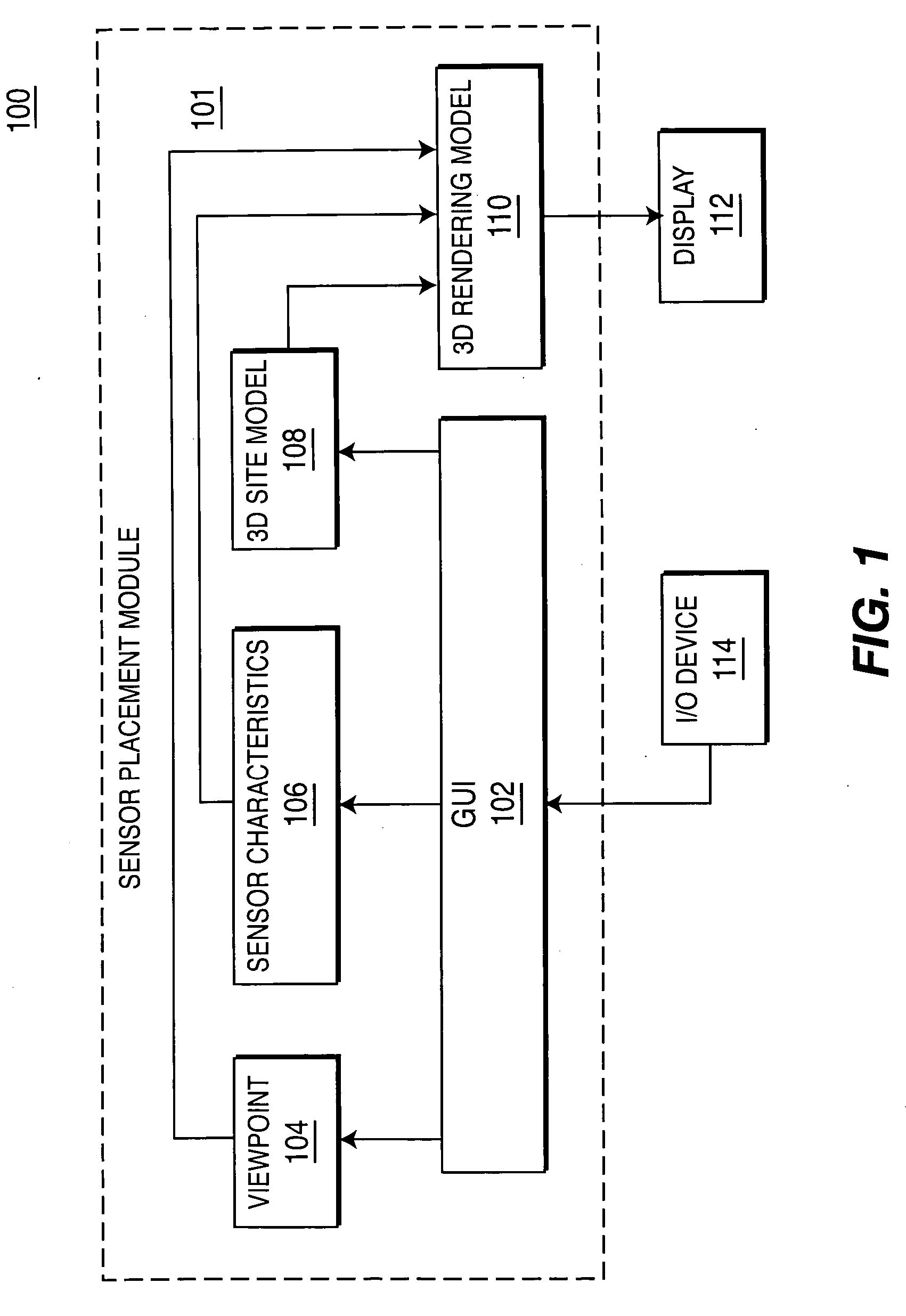
[0022]FIG. 1 depicts a high level block diagram of a sensor placement system 100 in accordance with an embodiment of the invention. The system comprises a sensor placement module 101, one or more I / O devices 114, and a display 112. The system utilizes one or more I / O devices 114 for the input of information and / or adjustment of parameters by a user. The 0I / O de...


PUM


Abstract

Method and apparatus for dynamically placing sensors in a 3D model is provided. Specifically, in one embodiment, the method selects a 3D model and a sensor for placement into the 3D model. The method renders the sensor and the 3D model in accordance with sensor parameters associated with the sensor and parameters desired by a user. In addition, the method determines whether an occlusion to the sensor is present.

Description

CROSS-REFERENCE TO RELATED APPLICATIONS [0001] This application claims benefit of U.S. provisional patent application Ser. No. 60 / 484,138, filed Jul. 1, 2003, which is herein incorporated by reference.BACKGROUND OF THE INVENTION [0002] 1. Field of the Invention [0003] Embodiments of the present invention generally relate to surveillance systems and, more particularly, relates to a method and apparatus for dynamically configuring sensor placement using a 3D model. [0004] 2. Description of the Related Art [0005] The current preferred method for optimizing the design of a sensor (e.g., a camera) layout is to begin with a 2D plan view of the environment, and to place cameras manually on the 2D plan view. In many cases, the design finishes at this point. In other cases, the desired field of views of the cameras are computed using a spreadsheet that computes the pixel size of an object given a camera's field of view using a 2D model of the environment. The cameras are then positioned at t...

Claims


Application Information

Patent Timeline
IPC IPC(8): G01RG02B7/28H04N7/18
CPCH04N7/181
Inventor ARPA, AYDINHANNA, KEITH J.SAMARASEKERA, SUPUNKUMAR, RAKESHSAWHNEY, HARPREET SINGH
Owner L 3 COMM CORP
Why Eureka
Try Eureka