
Orbital sander

a technology of orbital sanders and sanders, which is applied in the direction of grinding machines, metal-working apparatuses, grinding machine components, etc., to achieve the effect of facilitating us

Inactive Publication Date: 2005-01-06
EASTWAY FAIR
View PDF28 Cites 16 Cited by
  • Summary
  • Abstract
  • Description
  • Claims
  • Application Information

AI Technical Summary

Benefits of technology

[0010] The orbital sander further has a novel dust collection outlet port which facilitates the use of a dust collection cannister or two alternative sized dust collection vacuums.

Problems solved by technology

The relative concentration of fan blades in one region of the discs and the sparse spacing of fan blades in a diametrically opposite region results in an imbalance which is used to counter-balance the eccentrically offset sanding platen which is pivotally attached thereto without using a conventional balance weight.

Method used


Image

  • Orbital sander
  • Orbital sander
  • Orbital sander

Examples


Embodiment Construction

)

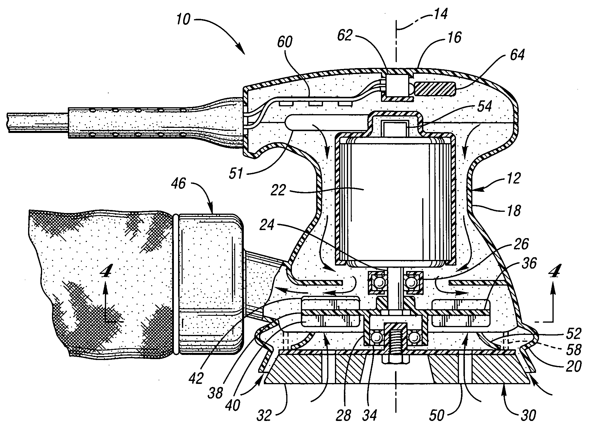
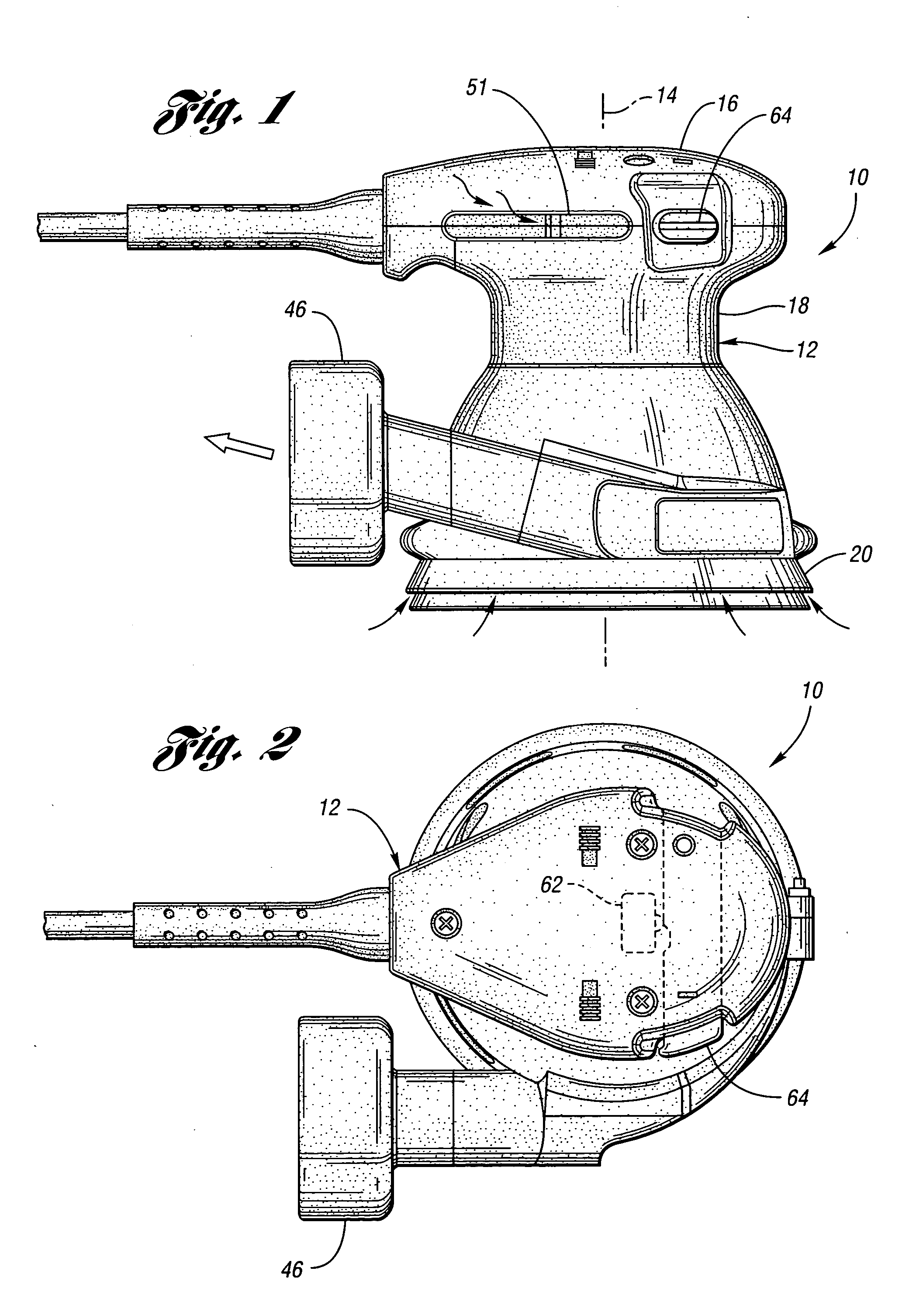
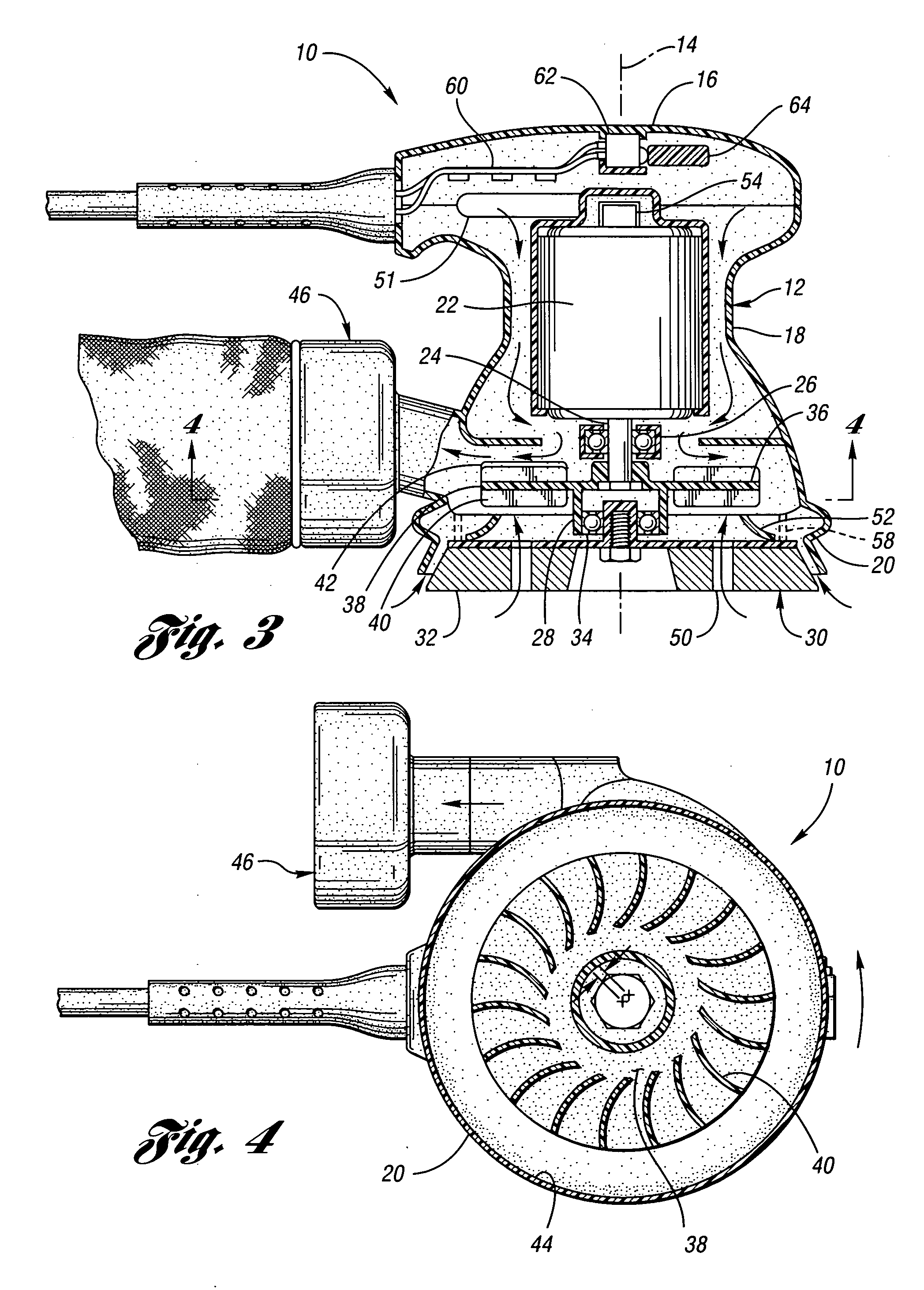
[0021] Random orbit palm sander 10 shown in FIGS. 1 through 4 illustrates a preferred embodiment of the invention. The random orbit palm sander 10 is made up of an elongate tubular housing assembly 12 which is aligned along a generally vertical central axis 14. The housing has an upper first end 16, a central tubular region 18 and a open lower second end 20. Oriented within housing assembly 12 and generally aligned with central axis 14 is a high speed permanent magnet DC motor 22. The motor has a generally cylindrical body sized to fit within the housing tubular portion 12 and a rotary motor output shaft 24. Motor output shaft 24 is affixed to eccentric drive hub 26 which has an output member 28 which is eccentrically offset from the motor central axis. A sanding platen 30 is oriented adjacent to housing second end 20. This sanding platen 30 has a planar surface 32 which is perpendicular to central axis 14 and is adapted to receive sandpaper. Interposed between the eccentric drive ...


PUM


Abstract

An orbital sander is provided having a number of novel features including a high speed permanent magnet DC motor having a relatively flat rpm versus torque curve. The sander includes an AC to DC power supply, a remotely located on / off switch operated by a switch actuator bar extending transversely through the housing enabling the operator to actuate the on / off switch by alternatively pushing opposed ends of the actuator bar. The orbital sander further includes a fan having non-uniformly spaced blades, eliminating the need for a conventional counterweight, and a dust outlet adapted to be alternatively connected to a dust canister or alternate size collector vacuum hoses.

Description

BACKGROUND OF THE INVENTION [0001] 1. Field of the Invention [0002] This application relates to orbital tools and in particular, small hand-held palm sanders. [0003] 2. Background Art [0004] Orbital palm sanders are widely used for a variety of sanding operations from woodworking to auto body repair. Orbital palm sanders come in two general types; random orbit sanders and pad sanders. Random orbit sanders typically have a round sanding platen which supports a sandpaper disc mounted on a central pivot bearing which is rotated about an orbital path. The sanding platen moves in an orbital pad but, is otherwise free to rotate about the bearing. Pad sanders are typically very similar in construction to a palm-type random orbit sander, however, the sanding platen is constrained so that it can orbit, but cannot freely rotate relative to the housing. An example of such a tool is a quarter sheet sander having a generally square sanding platen. A third variant, although not common, is an ecce...

Claims


Application Information

Patent Timeline
Patent Type & Authority Applications(United States)
IPC IPC(8): B24B23/03B24B55/10
CPCB24B55/102B24B23/03
Inventor DUTTERER, DAVID ERICPEOT, DAVID G.BRAZELL, KENNETH M.BOSTIC, ERNEST CHANDLERMCQUINN, MICHAEL HALBERTWACKER, CHARLES M.
Owner EASTWAY FAIR
Learn More