Dual-chamber liquid receiving and containing device

a liquid receiving and containing device technology, applied in medical science, surgery, vaccination/ovulation diagnostics, etc., can solve the problem of inaccurate bacteriological analysis results

Inactive Publication Date: 2005-01-06
BIOMARKETING SERVICES M SDN BHD
View PDF7 Cites 11 Cited by
  • Summary
  • Abstract
  • Description
  • Claims
  • Application Information

AI Technical Summary

Benefits of technology

[0008] A dual-chamber liquid receiving and retaining device comprises a liquid receiving and retaining body having an open top and an open bottom. A generally funnel-shaped transverse inner wall divides the body into an upper liquid receiving and retaining chamber and a lower liquid receiving and retaining chamber, the transverse inner wall having a central orifice which enables liquid flow communication between the upper and lower chambers. An orifice stopper disposed in the lower chamber beneath the orifice is responsive to liquid filling the lower chamber to a predetermined level for causing the stopper to float upwardly into sealing engagement with the orifice for stopping liquid flow into the lower chamber.

Problems solved by technology

Assuming possibly unclean fore-stream urine is contained in the lower chamber and clean mid-stream urine, which is desired for bacterial analysis, is contained in the upper chamber, any such bleeding of the fore-stream urine from the lower chamber past the orifice stopper could contaminate the mid-stream urine contained in the upper chamber, rendering its bacteriological analysis results inaccurate.

Method used


Image

  • Dual-chamber liquid receiving and containing device
  • Dual-chamber liquid receiving and containing device
  • Dual-chamber liquid receiving and containing device

Examples


Embodiment Construction

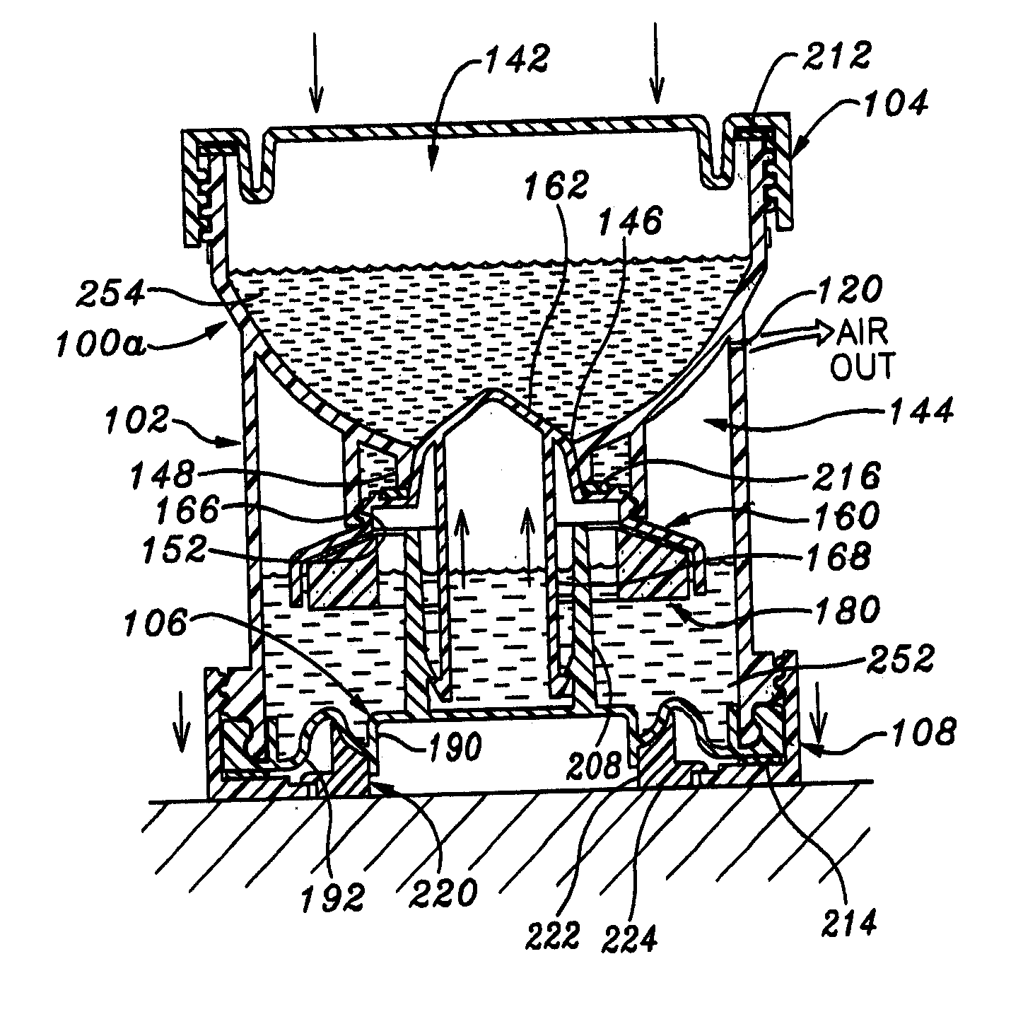
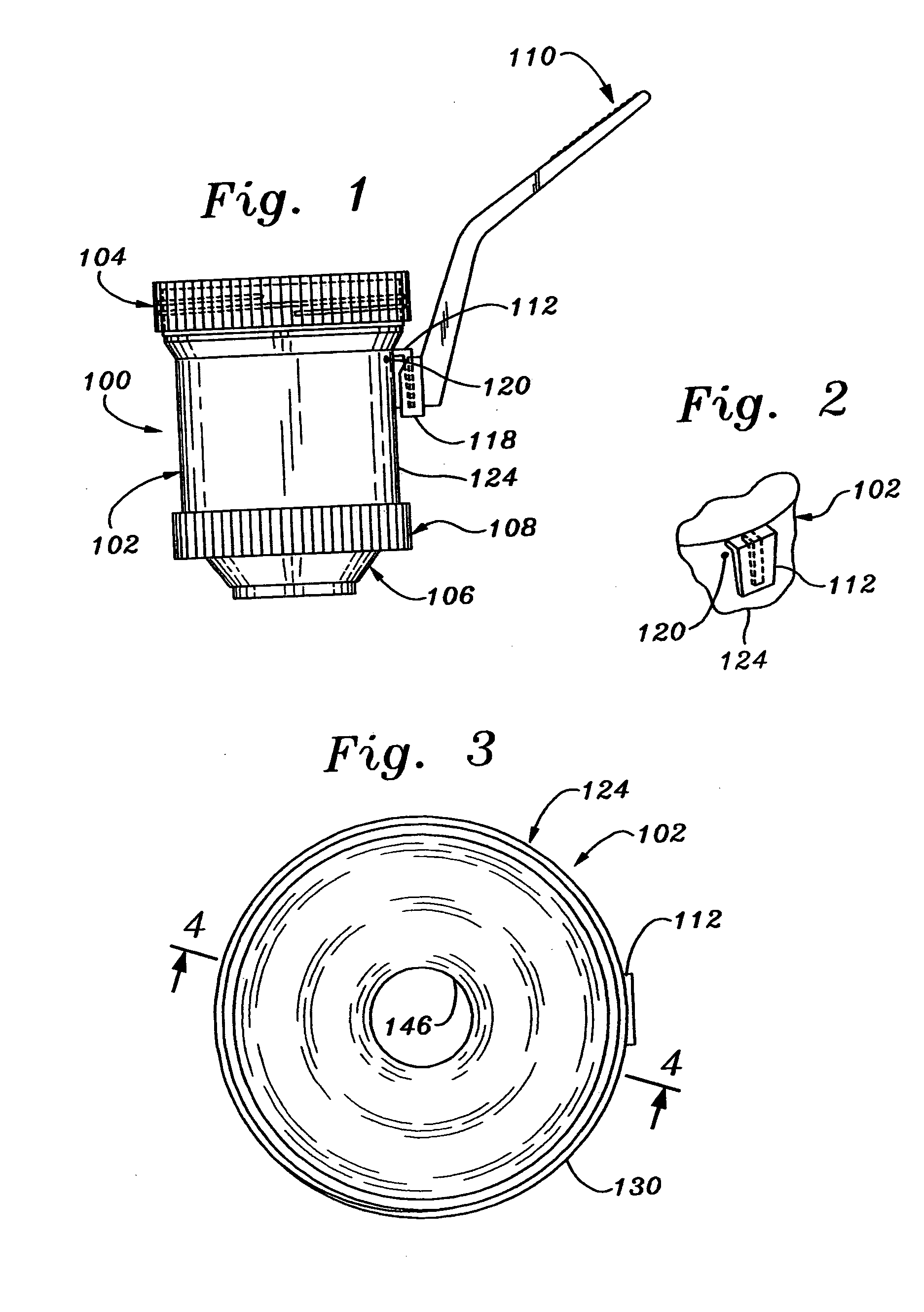
[0021] There is shown in FIG. 1 a dual-chamber, liquid receiving and containing device 100 (hereinafter, for the sake of brevity, usually referred to as the “dual-chamber device”) which may advantageously be used to receive a flow of urine from a patient and contain the urine flow as separate fore-stream and mid-stream flow portions, as described below.

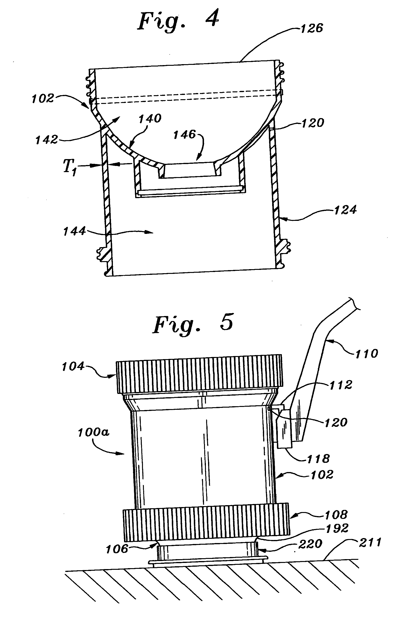
[0022] Shown comprising dual-chamber device 100 are a generally cylindrical device body or liquid cup 102, a top cover or cap 104 that is detachably attached at an open upper end of the body, a bottom cover or cap 106 that is attached to an open bottom of the body, a bottom cover locking ring 108 that is threaded onto the body to secure the bottom cover to the body and an angled handle 110 that is detachably attached to the body by a tapered fitting 112 projecting from upper regions of the device body. Shown adjacent fitting 112 is a microscopic pressure relief hole 120 that extends through a device body outer wall 124 at the highest...


PUM


Abstract

A dual-chamber device for receiving and containing a liquid, particularly urine, employs a generally cylindrical body having a detachable top cover and an internal, transverse, funnel-shaped wall. The transverse wall has a central circular orifice and divides the body into lower and upper chambers for respectively receiving and retaining fore-stream and mid-stream urine liquid samples. A floatable orifice stopper in the lower chamber is responsive to fore-stream liquid filling the lower chamber to a predetermined level for closing the orifice, so that subsequent, mid-stream urine liquid is received into the upper chamber. A bottom cover has an upstanding stopper pushing column and a flexible, spring-like, annular web around a bottom cover pedestal region. When the urine liquid has been collected in the device and the device is pushed downwardly onto the bottom cover pedestal region, the web flexes, causing the bottom cover column to force the stopper tightly into the orifice, and locks over center to positively lock the stopper into the orifice to prevent leakage between the two chambers. A microscopic hole in the device body wall substantially above the predetermined urine level in the lower chamber vents air pressure from the lower chamber when the bottom cover is flexed to force the stopper into the orifice.

Description

[0001] This application is a continuation in part (CIP) of application Ser. No. 10 / 834,405, filed Apr. 29, 2004, which is in turn a utility application converted from provisional application Ser. Nos. 60 / 483,782 and 60 / 494,773, filed respectively on Jun. 28, 2003 and Aug. 13, 2003. Application Ser. No. 10 / 834,405 (parent application) is incorporated herein in its entirety by specific reference.FIELD OF THE INVENTION [0002] The present invention relates to the general field of devices for collecting and separately containing dual samples of a liquid, more particularly to the collection and separately containing of dual samples of body fluids, and still more particularly to the collection and separate containing of dual samples of urine for analysis. BACKGROUND DISCUSSION [0003] In our above-cited parent application, there is disclosed a dual chamber device for collecting and retaining two sequential samples of liquid, in particular fore-stream and mid-stream samples of urine from an ...

Claims


Application Information

Patent Timeline
Patent Type & Authority Applications(United States)
IPC IPC(8): A61B10/00
CPCA61B10/007
Inventor YONG, PETER A. K.RISPLER, MARK J.
Owner BIOMARKETING SERVICES M SDN BHD
Why Eureka
Try Eureka