Damping brace and structure

a technology of axial force member and axial force member, which is applied in the direction of shock absorption, mechanical equipment, shock absorption, etc., can solve the problems of inability to provide the stiffness and yield strength, inability to adequately absorb vibrational energy, and inability of the axial force member to function as expected, so as to increase the stiffness of the axial force member and prevent adhesion

Active Publication Date: 2005-01-13
NIPPON STEEL CORP
View PDF2 Cites 44 Cited by
  • Summary
  • Abstract
  • Description
  • Claims
  • Application Information

AI Technical Summary

Benefits of technology

[0011] The damping brace according to an exemplary embodiment of the present invention includes an axial force member which provides yield strength against tensile or compressive forces acting in the axial direction. A constraining member is also provided which is arranged over the periphery of the axial force member and constrains the axial force member. Further, a stiffening part is provided on the external portion(s) of the axial force member and increases the stiffness of the axial force member; and an adhesion-preventing coating which is provided between the constraining member and the stiffening part and prevents adhesion between them. The length of the stiffening part in the axial direction and the size of the gap between the stiffening part and the constraining member are such that the external portion(s) of the axial force member will not rotate beyond a certain angle relative to the axial direction when the axial force member is subjected to the compressive forces.

Problems solved by technology

The external portion(s) of the axial force member exhibit unstable behavior, and the damping brace cannot provide the stiffness and yield strength intended in the design and becomes unable to adequately absorb the vibrational energy.
A gap may be used between the constraining member and the stiffening part since if there is no gap between these elements, the axial force member may not be able to function as expected.
Furthermore, if the length of the stiffening part in the axial direction is shorter than 150 mm, end breakage of the axial force member will likely occur.

Method used


Image

  • Damping brace and structure
  • Damping brace and structure
  • Damping brace and structure

Examples


first exemplary embodiment

[0048] First Exemplary Embodiment

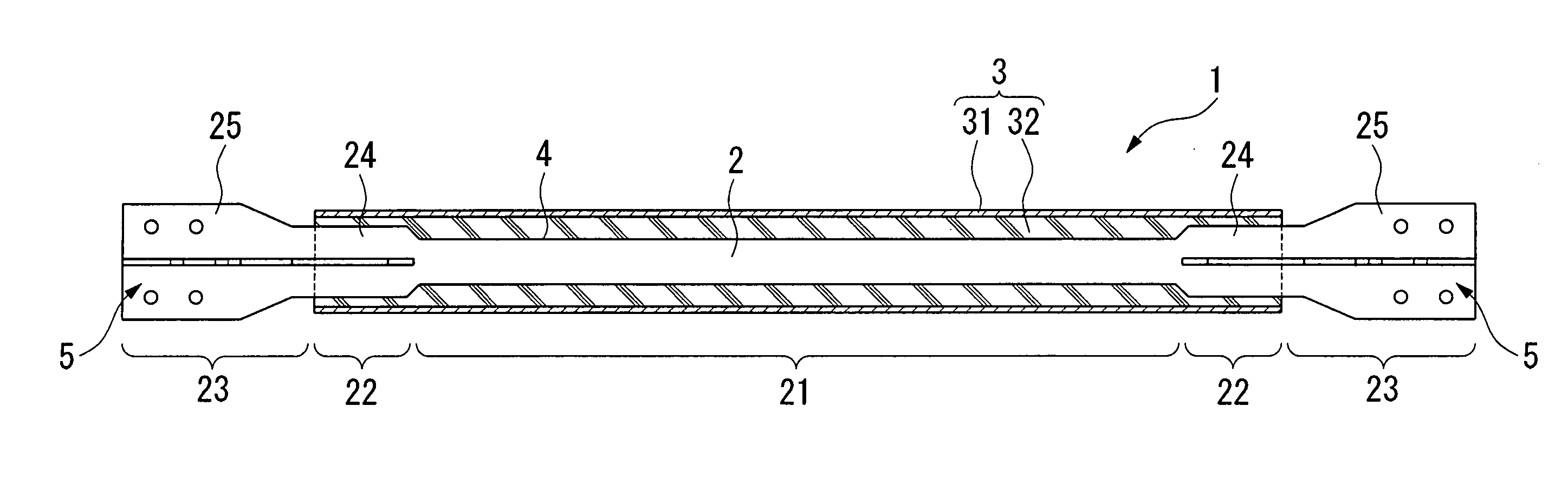
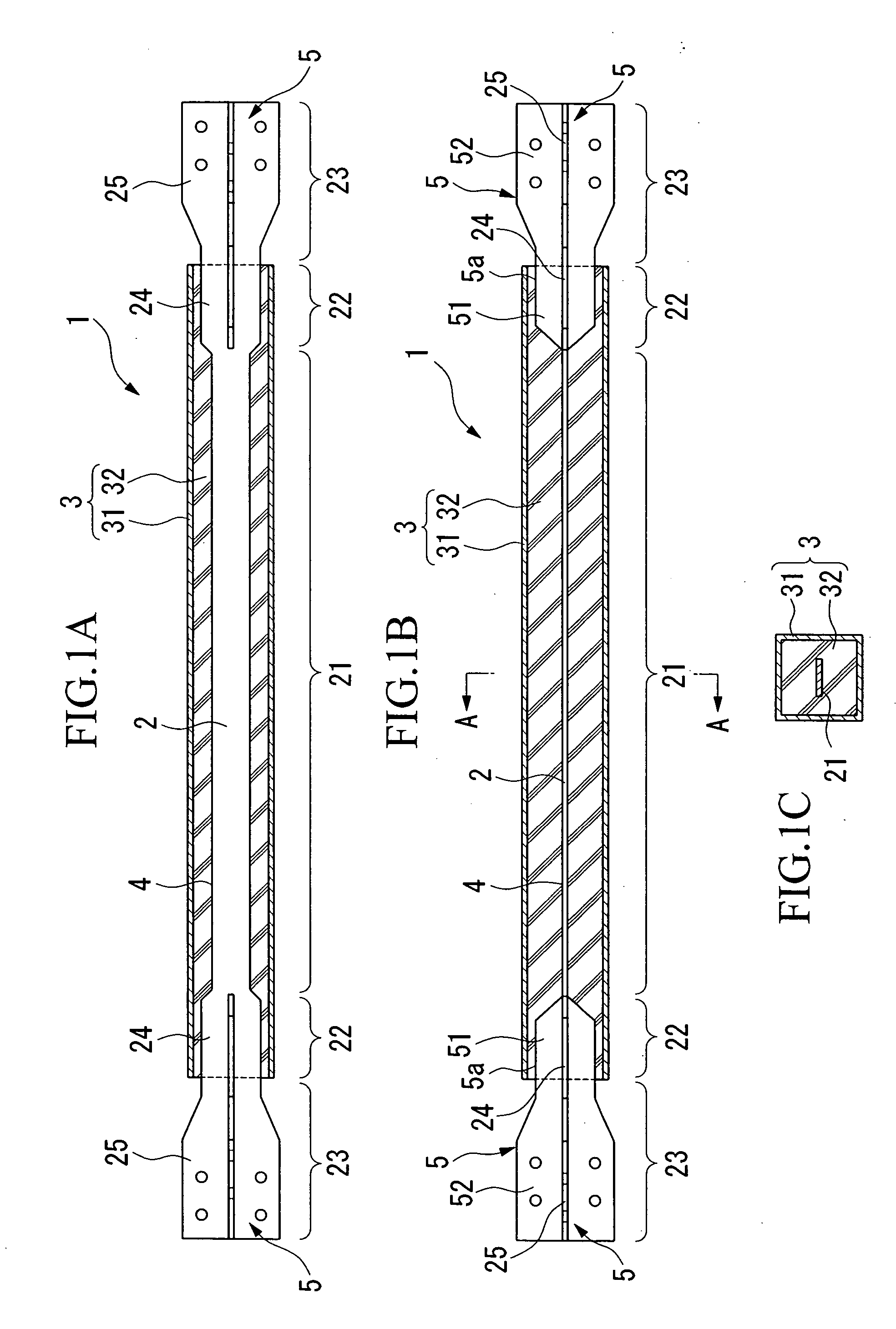
[0049] A damping brace 1, as shown in FIGS. 1(A)-(C), includes an axial force member 2 which provides yield strength against tensile or compressive forces acting in the axial direction, and a constraining member 3 which is provided over the periphery of the axial force member 2 and constrains the axial force member 2. Between the axial force member 2 and constraining member 3, an adhesion-preventing coating 4 is provided, which can prevent the adhesion therebetween.

[0050] The axial force member 2 is covered by constraining member 3, and includes a yielding part 21 which undergoes yielding and absorbs energy when subjected to tensile or compressive forces above a certain magnitude. The axial force member 2 also includes a stiffening part 22 which increases the stiffness of the yielding part 21 protruding from the constraining member 3; and a coupling part 23 which is provided on the outside of the stiffening part 22 and is joined to the structure.

[0...

second exemplary embodiment

[0067] Second Exemplary Embodiment

[0068] A second exemplary embodiment of the present invention will be described with reference to the drawings. Components already described in for the first exemplary embodiment of the present invention will be designated with the same symbols, and thus have already been described above.

[0069] In the damping brace 1 of this exemplary embodiment, stiffening ribs 53 of approximately the same length as the axial force member 2 are provided, as shown in FIG. 9(A), (B). The stiffening ribs 53 are made from a steel sheet of uniform thickness just like the axial force member 2, and have a shape that links the two stiffening ribs 5 provided at the two external portion(s) of the axial force member 2 via a coupling bar 54 arranged along the yielding part 21. The stiffening ribs 53 are arranged on two sides of the axial force member 2, and are welded at the portion abutting on the axial force member 2 in the axial direction. The coupling bar 54 increases the...

third exemplary embodiment

[0072] Third Exemplary Embodiment

[0073] A third embodiment of the present invention will be described with reference to the drawings. Components already described in the preceding first and second embodiments will be designated with the same symbols, and thus have already been described above.

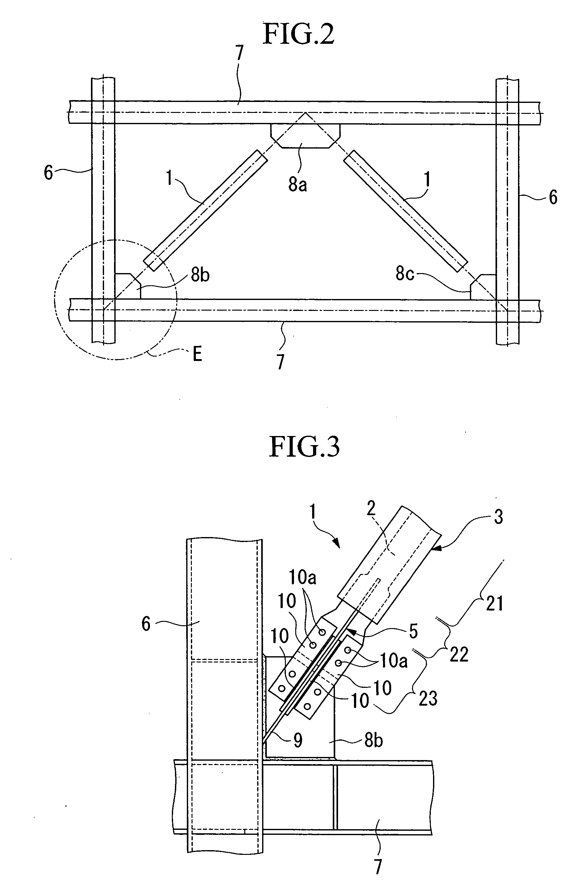
[0074] In the damping brace 1 of this exemplary embodiment, two axial force members 2 are provided, as shown in FIG. 11(A), (B). These two axial force members 2 are arranged in parallel at an equal spacing, and each axial force member 2 is provided with one stiffening rib 5. When installing this damping brace 1 in a structure, a gusset plate 8a (or members 8b, 8c) is inserted between the external portion(s) of the two axial force members 2, which are bolted without using any splice plates. The stiffening ribs 5 may be bolted using splice plates.


PUM

PropertyMeasurementUnit
lengthaaaaaaaaaa
sizeaaaaaaaaaa
sizeaaaaaaaaaa

Abstract

A damping brace having an axial force member for providing bearing forces against tensile or compressive forces, a constraining member for constraining the axial force member, and a stiffening part for supplementing the stiffness of the axial force member. An adhesion preventive coating is provided for preventing adhesion between the constraining member and the stiffening part. A length of the stiffening part extending along the axial direction and the gap between the stiffening part and the constraining member are defined in such a way as to prevent an end of the axial force member from rotating in the axial direction beyond a specific angle when the compressive force is applied to the force member.

Description

CROSS-REFERENCE TO RELATED APPLICATION(S) [0001] The present application claims priority under 35 U.S.C. § 119 from Japanese Patent Application No. 2003-193274, filed on Jul. 8, 2003, the entire disclosure of which is incorporated herein by reference.FIELD OF THE INVENTION [0002] The present invention relates to a damping brace that deforms itself to absorb vibrational energy applied to a building structure from earthquakes, winds and the like, and a structure which includes such brace. BACKGROUND INFORMATION [0003] A typical conventional damping brace may include a steel axial force member, a constraining member for preventing buckling of the axial force member, and an adhesion preventive coating for preventing adhesion between the constraining member and the axial force member. The axial force member may include a yielding part for deforming yielding when a tensile force or a compressive force that exceeds a specified magnitude is applied, a stiffening part for stiffening an end o...

Claims


Application Information

Patent Timeline
Patent Type & Authority Applications(United States)
IPC IPC(8): E04H9/02F16F7/00
CPCE04H9/028F16F2230/16F16F2224/025F16F7/00E04H9/0237
Inventor NAKAMURA, HIROSHISUZUKI, KAZUAKINAKATA, YASUHIROSHIRAI, TAKASHI
Owner NIPPON STEEL CORP
Why Eureka
Try Eureka