Power cable assembly for water and air-cooled welding torches

a technology for water and air-cooled welding torches, which is applied to power cables, cables, insulated conductors, etc., can solve the problems of cable size, bulk and weight, and less efficient cooling conditions, and achieves the effects of reducing fraying of wire cables, preventing clogging of water passageways or connector fittings, and enhancing water cooling efficiency

Inactive Publication Date: 2005-01-13
REHRIG RICHARD B
View PDF7 Cites 12 Cited by
  • Summary
  • Abstract
  • Description
  • Claims
  • Application Information

AI Technical Summary

Benefits of technology

[0007] Briefly, the present invention comprises a power cable assembly for water and air-cooled TIG, MIG and plasma torches. In water-cooled torch applications, the cable assembly is comprised of a flexible outer tube or hose for carrying cooling water from the torch head back to the circulator reservoir, a copper cable of a smaller diameter disposed within the conduit for electrically communicating the torch head with the welding machine and a thin coating of a flexible plastic material encapsulating the copper cable. The coating reduces fraying of the wire cable due to flexing and hydrogen embrittlement and contains any wire splinters that may break off during use to prevent clogging of any water passageways or connector fittings. The plastic coating also defines a plurality of radial projections extending therefrom so as to abut the interior wall of the outer conduit so as to position the cable within the conduit such that the water passing therethrough flows completely about the copper cable, cooling the entire surface of the cable, significantly enhancing the water cooling efficiency. In air-cooled torch applications, the plastic coating and radial projections position the cable within the conduit such that the gas passing therethrough completely surrounds the cable to enhance the cooling of the cable. In both water and air applications, additional electrical insulation is provided in addition to the centering of the electrical cable within the conduit to inhibit grounding.

Problems solved by technology

This results in a less efficient cooling condition than would exist if the cable were completely surrounded by the flowing cooling water.
As a result of this relatively inefficient cooling of the cable, the cable must be relatively large in size to maintain the desired level of current capacity.
The larger cable also adds bulk and weight to the power cable assembly and the welding torch resulting in less flexibility and added operator fatigue.
This constant movement causes the fine copper wires of the cable to work harden and fracture.
The problem is compounded by the fact that the cooling water passing over the copper causes hydrogen embrittlement.
The wire splinters are carried by the cooling water flow to the end fitting on the power cable assembly where they collect and block the water flow through the fitting and cause overheating and torch failure.
The use of other copper wire alloys that are less susceptible to hydrogen embrittlement, such as oxygen-free copper, has not resulted in appreciable improvement.
While this cooling of the electrical cable by the flowing gas is not as efficient as the cooling effected by the flowing water in water-cooled torches, it does have a cooling effect.
As with the water-cooled torches, the efficiency of this cooling effect is adversely affected by the contact between the cable and the inside bore of the outer tube or hose which prevents the gas from completely surrounding the cable as it flows thereby.
HF current travels on the surface of the copper cable and is prone to leak or go to ground anywhere along the cable as the cable lays on the floor or workbench.

Method used


Image

  • Power cable assembly for water and air-cooled welding torches
  • Power cable assembly for water and air-cooled welding torches
  • Power cable assembly for water and air-cooled welding torches

Examples


Embodiment Construction

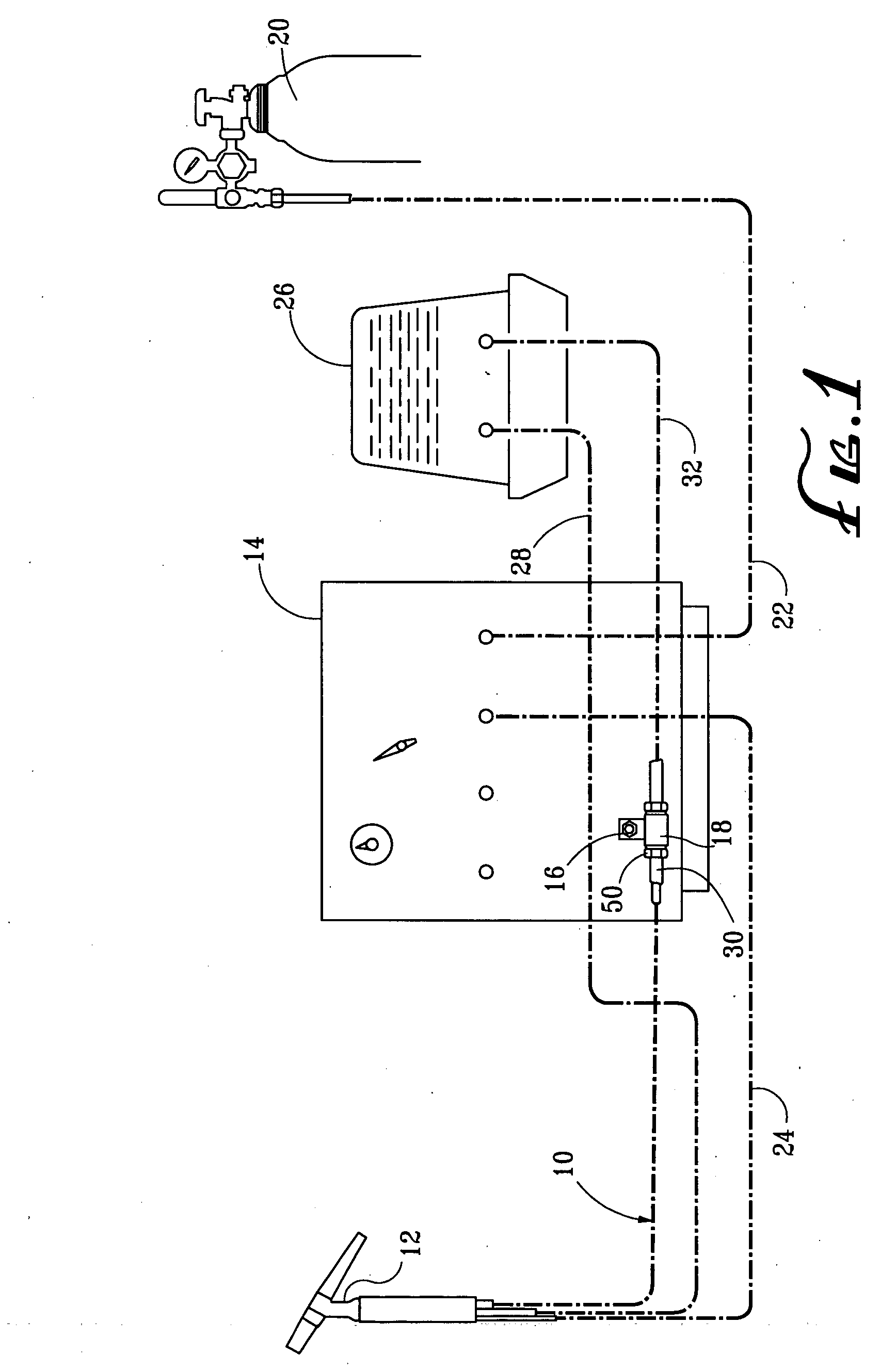
[0012] Referring now in detail to the drawings, a typical power cable application in a water-cooled TIG welding assembly is illustrated in FIG. 1. As seen therein, the power cable assembly 10, to which the present invention is directed, extends between and electrically communicates the welding torch 12 with the welding machine 14 by virtue of the direct connection between the power cable assembly and an output stud 16 on the welding machine through an electrically conductive adapter 18. The inert tungsten gas is provided to the torch 12 from gas supply 20 through lines 22 and 24 via the welding machine 14. Cooling water is provided to the torch from the circulator reservoir 26 via line 28. The water is returned to the reservoir 26 through the power cable assembly 10, a flow-through conduit portion 30 of adapter 18 and fluid-flow return line 32. As the water flows through the power cable assembly 10, it cools the electrically conductive cable disposed therein.

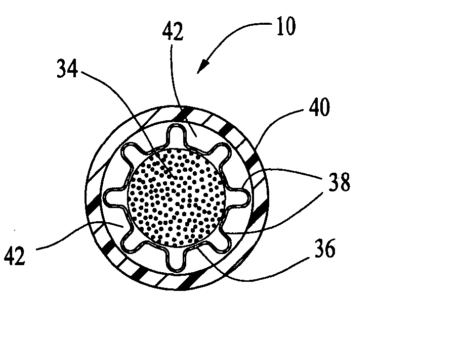
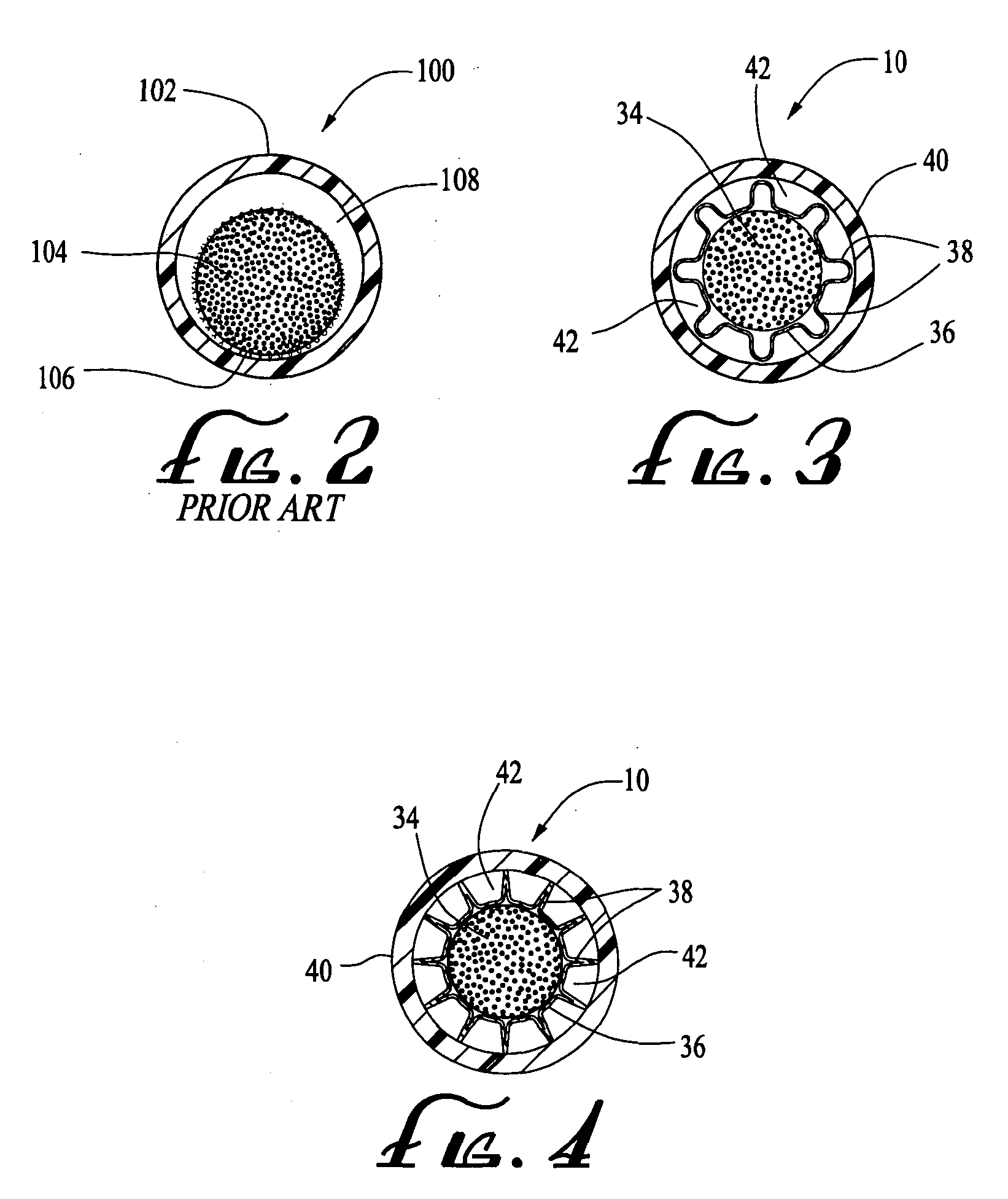
[0013] A cross-section ...


PUM

PropertyMeasurementUnit
lengthaaaaaaaaaa
diameteraaaaaaaaaa
flexibleaaaaaaaaaa

Abstract

A power cable assembly for use in a water and air-cooled welding assemblies for carrying power from a welding machine to a welding torch and either cooling water from the torch to a circulator reservoir or, in the case of air-cooled torches, shielding gas to the torch. The cable assembly includes a flexible outer conduit disposed about a flexible electrical conductor formed of a plurality of twisted, braided or bunched wires encased in a thin layer of flexible plastic material. A plurality of projections extend radially from the flexible encasement so as to space the electrical conductor from the interior conduit wall, thereby defining a water or gas-flow path extending entirely about the conductor to enhance the efficiency of heat removal from the conductor.

Description

BACKGROUND OF THE INVENTION [0001] Welding torches of the water-cooled type used for TIG (tungsten inert gas), MIG (metallic inert gas) and plasma welding and cutting processes are typically connected to the power source (welding machine) with three or more lines. One line conveys cooling water to the torch head, a second line conveys the shielding gas to the torch head and the third line is used to transfer the electrical output from the power source or welding machine to the torch head. This third line also conveys cooling water back to the circulator reservoir. This third line is commonly referred to as the power cable. With plasma torches, there may be two power cables on each torch. These power cables are made from a flexible plastic tube or rubber hose that defines a conduit. Inside the conduit is a stranded copper cable formed of fine individual wires twisted or braided in a rope-like construction. The copper wires can be bare or plated. The copper cable functions as the elec...

Claims


Application Information

Patent Timeline
Patent Type & Authority Applications(United States)
IPC IPC(8): B23K9/32
CPCB23K9/323H01B9/001B23K2201/38B23K2101/38
Inventor REHRIG, RICHARD B.
Owner REHRIG RICHARD B
Why Eureka
Try Eureka