Procedure for exchanging useful information generated according to different coding laws between at least 2 pieces of user terminal equipment

a technology of user terminal equipment and useful information, which is applied in automatic exchange, telephonic communication, electrical equipment, etc., can solve problems such as the danger of falsifying useful information, and achieve the effect of efficient coding/decoding

Inactive Publication Date: 2005-01-13
NOKIA SIEMENS NETWORKS GMBH & CO KG
View PDF15 Cites 46 Cited by
  • Summary
  • Abstract
  • Description
  • Claims
  • Application Information

AI Technical Summary

Benefits of technology

[0013] One advantage of the invention is the fact that an efficient coding / decoding is carried out when switching over from the μ-law to the A-law while the CODEC negotiation procedure already existing in the Q.765.5 BAT protocol is extended by an additional logic. This ensures that the correct coding procedure is selected. With this additional logic for the correct selection of the Codecs, a switchover between the A-law and the μ-law coding firstly takes place. The additional logic transmits the transcoding rule for VoIP connections specified in the ‘TDM world’.
[0014] Another advantage of the invention is the fact that an efficient coding / decoding also takes place for fall back connections when switching over from the μ-law to the A-law while the CODEC negotiation procedure already existing in the Q.765.5 BAT protocol is extended by an additional logic.
[0015] Advantageous further developments of the invention are given in the subclaims.

Problems solved by technology

Therefore, problematical is the condition that the Q.1902.x BICC CS2 ITU-T standard does not consider the problem if the user of an A-law country would like to establish a connection to a user set up in a μ-law country.
Because in this case the information exchanged between both users is generated according to different coding laws, the danger of falsifying the useful information exists.

Method used


Image

  • Procedure for exchanging useful information generated according to different coding laws between at least 2 pieces of user terminal equipment
  • Procedure for exchanging useful information generated according to different coding laws between at least 2 pieces of user terminal equipment
  • Procedure for exchanging useful information generated according to different coding laws between at least 2 pieces of user terminal equipment

Examples


Embodiment Construction

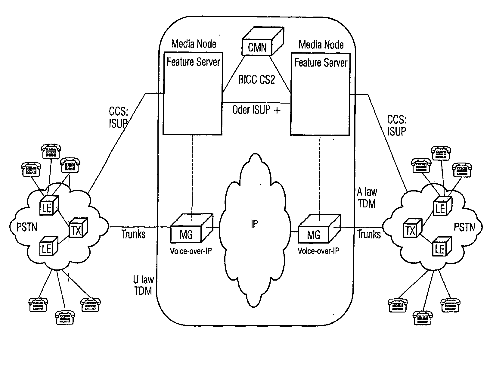
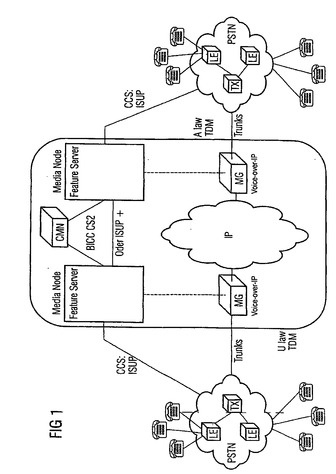
[0021]FIG. 1 shows a network configuration in which the procedure according to the invention takes place. Accordingly, 2 PSTN networks are shown in which several users are arranged in a well-known way in each case. These are routed to local switching centers LE that, on their part, are connected to transit switching centers TX.

[0022] Therefore, in the transit switching centers TX, the signaling information is separated from the useful information. The signaling information is fed directly from the transit switching center TX (ISUP protocol) to a media gateway controller CFS. The useful information is fed to a (arranged on the input-side) media gateway MG A that functions as an interface between the TDM network and a transmission network IP. The useful information is transmitted package-oriented via the transmission network IP. The media gateway controller CFS A that is embodied as the call feature server controls the media gateway MG A.

[0023] The useful information is routed from ...


PUM


Abstract

If TDM connections are through-connected from the originating TDM network to the target TDM network via a data network in the form of backbone, e.g. VoIP, the switchover between the TDM network and the data network takes place via media gateways. As is the case with connections exclusively between TDM, the coding algorithms of the A face and the B face have to be identical. In TDM networks, coding is done according to A Law and μ Law. When switching from an A Law network to a μ Law network, the coding specifications have to be converted. In order to carry out a conversion in a TDM environment, at the switchover point the μ Law face has to convert to A Law. The same applies to VoIP. The invention relates to the integration of this switchover conversion rule in the codec negotiation procedure so that in principle a μ Law A face offers μ Law and, alternatively, A-Law to the B face; a μ Law B face accepts μ Law whereas an A-Law B face acknowledges A-Law. Furthermore, 64 kBit/s unrestricted preferred connections are considered in fall back mode, wherefore an additional logic is integrated into the codec modification procedure by means of which in principle μ Law and, as an alternative, A-Law are offered to the B face in addition to the transparent CODEC or instead of offering a μ Law A face to the TMR only. The B face first accepts the transparent CODEC on the basis of the list or the TMR ‘64 kBit/s unrestricted preferred’. When receiving the TMU, the B face selects the Codec to satisfy the code conversion rule.

Description

CROSS REFERENCE TO RELATED APPLICATIONS [0001] This application is the US National Stage of International Application No. PCT / DE02 / 04200, filed Nov. 13, 2002 and claims the benefit thereof. The International Application claims the benefits of German application No. 10158059.2 filed Nov. 27, 2001, both of the applications are incorporated by reference herein in their entirety.FIELD OF INVENTION [0002] The invention relates to a procedure for exchanging useful information generated according to different coding laws between at least 2 pieces of user terminal equipment. BACKGROUND OF INVENTION [0003] More recent communication architectures separate switching networks into call feature servers and transport useful information (bearer control). Therefore, useful information can be transmitted via the different high-bit rate transport technologies such as ATM, IP or frame relay. [0004] With such a separation, telecommunications services transmitted in present narrowband networks must also...

Claims


Application Information

Patent Timeline
Patent Type & Authority Applications(United States)
IPC IPC(8): H04J3/16H04M3/00H04L29/06H04Q3/00
CPCH04M7/0072H04M7/122H04L65/103H04L65/1043H04M7/123
Inventor HOFFMANN, KLAUSSABROWSKI, SVENSTUPKA, JEAN-MARIE
Owner NOKIA SIEMENS NETWORKS GMBH & CO KG
Why Eureka
Try Eureka