Electrical connector with double mating interfaces for electronic components

a technology of electrical connectors and electronic components, applied in the direction of two-part coupling devices, coupling device connections, securing/insulating coupling contact members, etc., can solve the problems of increasing the difficulty of assembling/disassembling the transceiver to/from the mother board, the connector must be disassembled from the mother board and discarded, and the cost of using and maintaining the transceiver increases. , to achieve the effect of easy mounting/disass

Inactive Publication Date: 2005-01-13
HON HAI PRECISION IND CO LTD
View PDF12 Cites 90 Cited by
  • Summary
  • Abstract
  • Description
  • Claims
  • Application Information

AI Technical Summary

Benefits of technology

[0010] Another object of the present invention is to provide an electrical connector having a plurality of contact modules, any one or more of which can be readily removed from the connector and replaced by a substitute without damaging the connector.
[0011] A further object of the present invention is to provide an electrical connector, which can be readily mounted / disassembled to / from a circuit substrate such as a mother board.

Problems solved by technology

This increases the difficulty of assembling / disassembling the transceiver to / from the mother board.
If one of the contacts is damaged, the connector must be disassembled from the mother board and discarded.
This increases the costs of using and maintaining the transceiver.
Additionally, with ongoing developments in the electronics industry, requirements for transmission performance of transceivers are becoming more demanding.

Method used


Image

  • Electrical connector with double mating interfaces for electronic components
  • Electrical connector with double mating interfaces for electronic components
  • Electrical connector with double mating interfaces for electronic components

Examples


Embodiment Construction

[0025] Reference will now be made to the drawings to describe the present invention in detail.

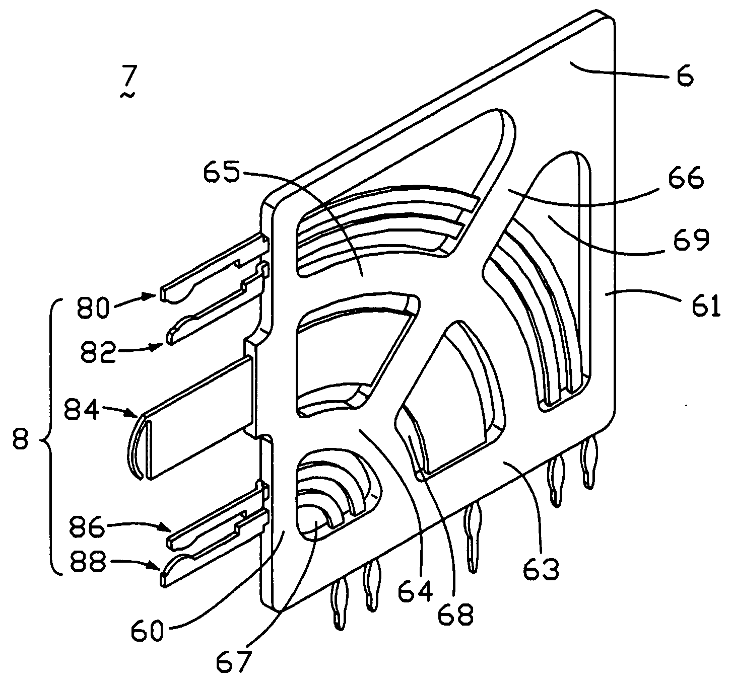
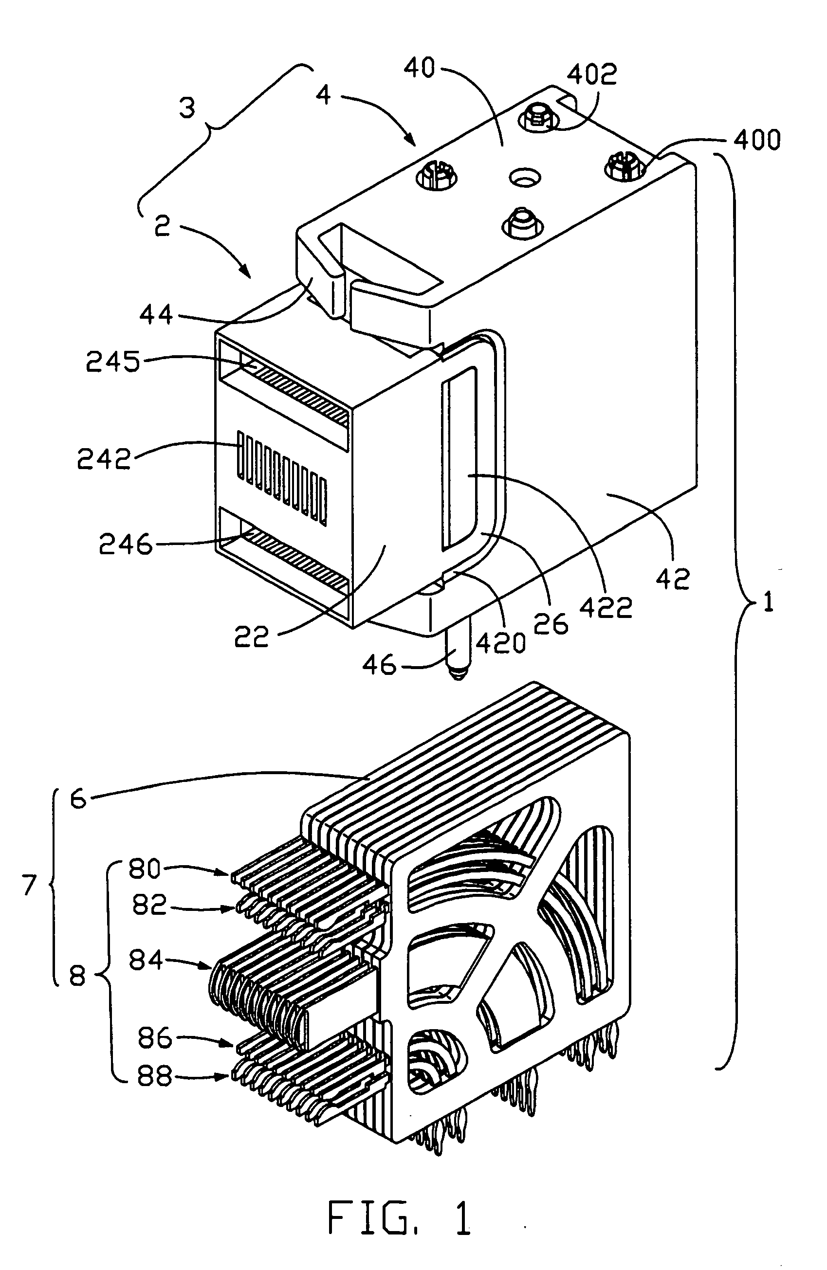
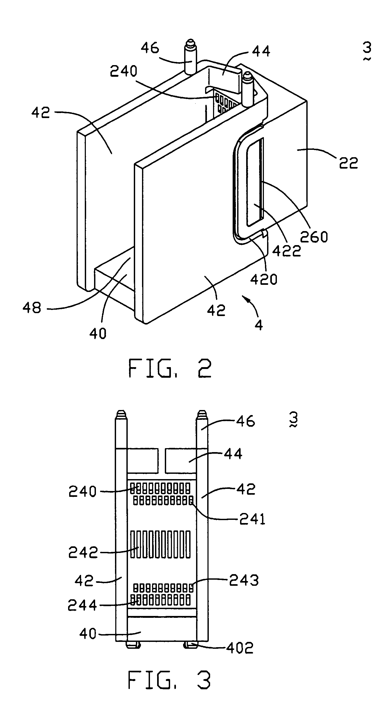
[0026]FIG. 1 is an exploded, isometric view of an electrical connector 1 in accordance with the preferred embodiment of the present invention. The connector 1 is used in a transceiver (not shown) that can provide bi-directional transmission of data between an electrical interface and an optical data link for networking applications. Generally, the transceiver includes a parallelepiped-shaped metallic shielding cage (not shown), a plurality of receptacles (not shown) stacked in a front portion of the cage for providing mating interfaces for a plurality of transceiver modules, a plurality of daughter boards (not shown) mounted at rear portions of the receptacles and extending rearward in the cage, and the connector 1 mounted in a rear portion of the cage. The daughter boards can convert electrically encoded data signals into optical signals. The daughter boards can also convert optically enc...


PUM


Abstract

An electrical connector (1) includes an insulative housing (3) mounted onto a mother board, and a mulitiplicity of contact modules (7) received in the housing. The housing defines first and second openings (245, 246) in a front portion thereof. Each contact module includes first, second, third and fourth contacts (80, 82, 86, 88) and a ground contact (84). The first and second contacts are inserted into the first opening to form a first signal contact group, thereby providing a first mating interface for a daugher board. The third and fourth contacts are inserted into the second opening to form a second signal contact group, thereby providing a second mating interface for another daughter board. The ground contacts are disposed betweent the first and second signal contact groups. The connector can thereby electrically connect the daughter boards with the mother board simultaneously.

Description

BACKGROUND OF THE INVENTION [0001] 1. Field of the Invention [0002] The present invention relates to the art of electrical connectors, and particularly to electrical connectors used in small form-factor pluggable (SFP) transceivers that provide bi-directional transmissions of data between electrical interfaces and optical data links for networking applications, wherein the connectors are generally used for receiving electronic components such as daughter boards and electrically connecting said electronic components with circuit substrates such as mother boards. [0003] 2. Description of the Prior Art [0004] Various international and industry standards define transceivers that provide bi-directional transmissions of data between electrical interfaces and optical data links for networking applications. One type of transceiver developed by an industry consortium is known as the small form-factor pluggable (SFP) transceiver. A correlative article is found in Taking the NETWORK to the Nex...

Claims


Application Information

Patent Timeline
Patent Type & Authority Applications(United States)
IPC IPC(8): H01R12/16H01R13/40H01R13/514H01R13/648
CPCH01R13/514H01R12/716H01R23/6873H01R13/6587
Inventor CHIEN, CHIH-MINGWANG, YI-WEN
Owner HON HAI PRECISION IND CO LTD
Why Eureka
Try Eureka