Connector

a technology of connecting rods and connectors, applied in the field of connecting rods, can solve the problems of increasing the inserting force and insufficient locking force of the terminal fittings, and achieve the effect of preventing excessive deformation of the lock

Active Publication Date: 2005-01-13
SUMITOMO WIRING SYST LTD
View PDF5 Cites 4 Cited by
  • Summary
  • Abstract
  • Description
  • Claims
  • Application Information

AI Technical Summary

Benefits of technology

[0008] The lock engages the locking projection when the terminal fitting is inserted to the proper depth in the cavity. Thus, the terminal fitting can be held with a sufficient locking force.
[0009] A degree of resilient deformation of the lock during insertion of the terminal fitting is made smaller by the depth of the recess. As a result, an inserting force for the terminal fitting is reduced. Further, the deformation of the lock can be reduced maximally since the sliding-contact surfaces of the locking projection and the recess have substantially conforming shapes.
[0014] At least one excessive deformation preventing portion may be provided for engaging the lock before the lock is deformed beyond its resiliency limit to prevent excessive deformation of the lock.

Problems solved by technology

Locking forces on the terminal fittings may be insufficient if the locks are made smaller in an effort to miniaturize the connector.
However, this design increases an inserting force because the lock must be deformed by an additional amount dictated by the projecting distance of the projection.

Method used


Image

  • Connector
  • Connector
  • Connector

Examples


Embodiment Construction

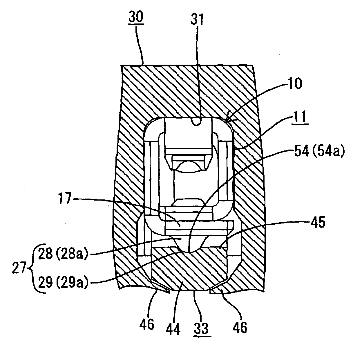
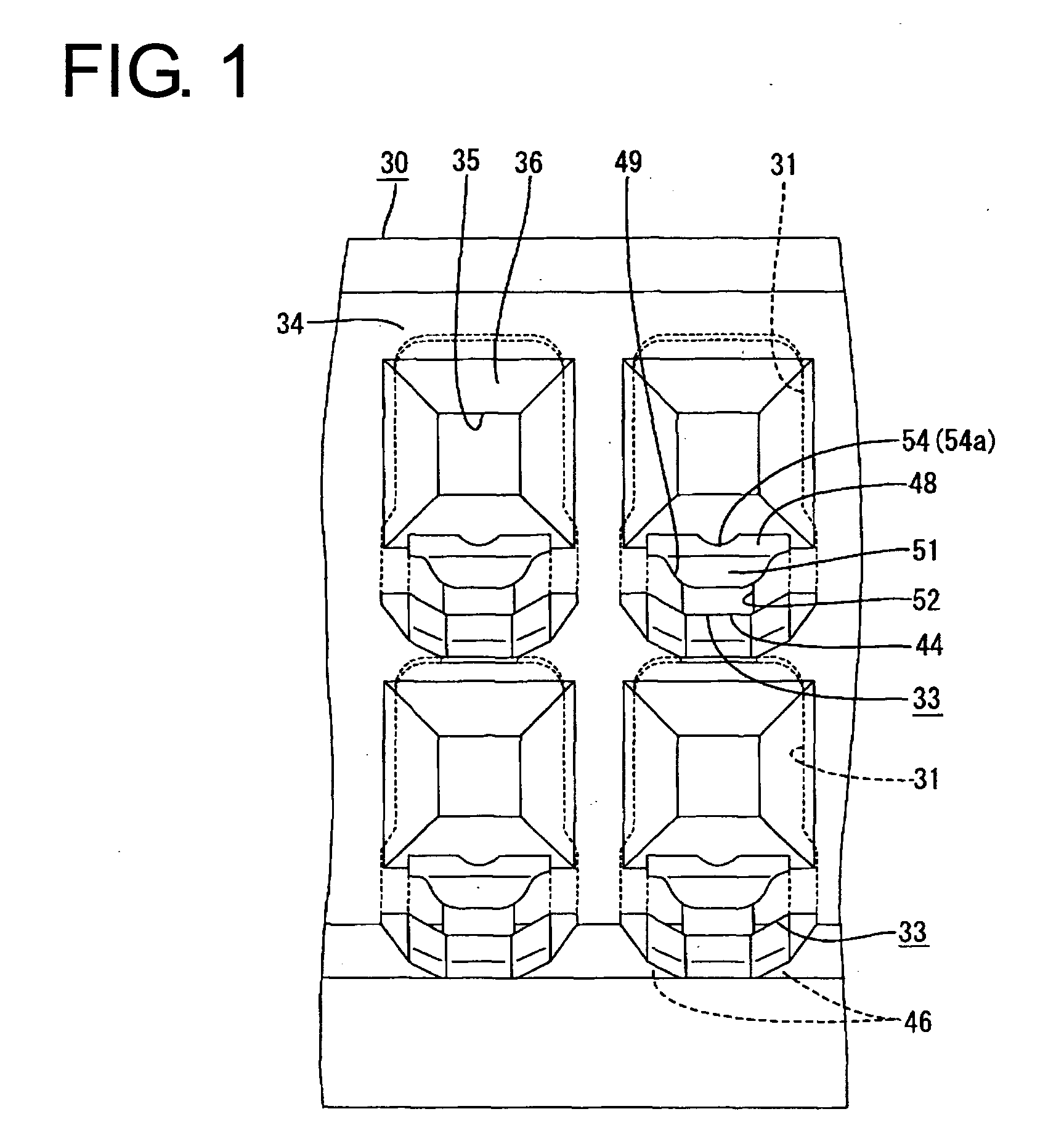
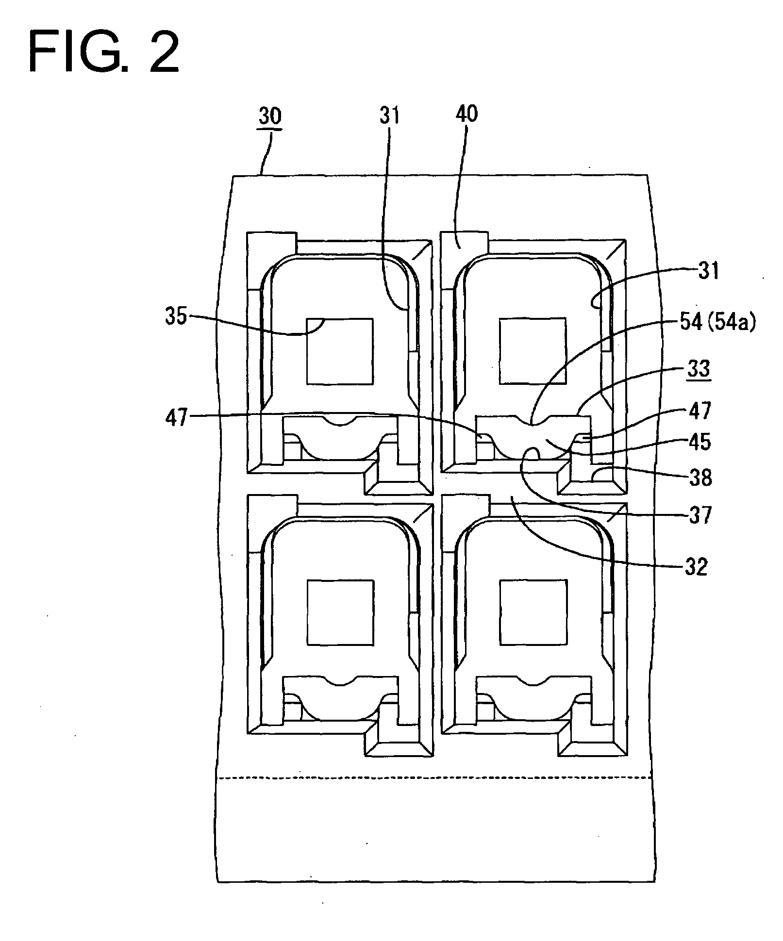
[0031] A female connector according to the invention is described with reference to FIGS. 1 to 10. The connector is comprised of female terminal fittings 10, a housing 30 for accommodating the terminal fittings 10. In the following description, inserting and withdrawing directions of the terminal fittings 10 into the housing 30 are referred to as forward and backward directions, respectively.

[0032] Each terminal fitting 10 has a specified shape and is formed by press-working a conductive metal plate. The terminal fitting 10 has a substantially box-shaped main portion 11 with open front and rear ends and a barrel 12 configured to be crimped, bent or folded into connection with the end of a wire W, as shown in FIGS. 4 to 6. The barrel 12 has a pair of front crimping pieces and a pair of rear crimping pieces to be crimped, bent or folded into connection with a core and an insulation coating of the wire W, respectively.

[0033] The main portion 11 includes a bottom wall 13 extending sub...


PUM


Abstract

A housing (30) has cavities (31) for receiving terminal fittings (10), and a lock (33) is provided in each cavity (31). The terminal fitting (10) temporarily resiliently deforms the lock (33) when the terminal fitting (10) is inserted into the cavity (31). The lock (33) then is restored resiliently to engage the terminal fitting (10) when the terminal fitting (10) reaches a proper depth. An outer wall (17) of the terminal fitting (10) facing the lock (33) has a locking projection (27) projecting toward and engageable with the lock (33). A recess (54) is formed in a surface of the lock (33) that slides in contact with the locking projection (27) in an inserting process. An arcuate surface (29a) of the locking projection (27) and a bottom surface (54a) of the recess (54) have substantially conforming shapes.

Description

BACKGROUND OF THE INVENTION [0001] 1. Field of the Invention [0002] The present invention relates to a connector. [0003] 2. Description of the Related Art [0004] U.S. Pat. No. 5,336,540 relates to a connector with a housing formed with cavities for receiving terminal fittings. Resiliently deformable locks are formed with the housing and project into the cavities. The locks are deformed as the terminal fittings are inserted into the cavities. However, the locks are restored resiliently when the terminal fitting reaches a proper depth. The restored locks engage an engaging portion of the terminal fitting, and thereby prevent the terminal fitting from coming out. [0005] Locking forces on the terminal fittings may be insufficient if the locks are made smaller in an effort to miniaturize the connector. Locking forces can be enhanced by forming each terminal fitting with a projection that projects towards the lock. The lock engages both the engaging portion and projection, thereby enhanci...

Claims


Application Information

Patent Timeline
Patent Type & Authority Applications(United States)
IPC IPC(8): H01R4/18H01R13/428H01R13/187H01R13/42H01R13/422H01R13/432
CPCH01R4/185H01R13/11H01R13/432H01R13/4223
Inventor KOJIMA, EIJIATSUMI, KEIGONISHIDA, ATSUSHIMINAKATA, MASATO
Owner SUMITOMO WIRING SYST LTD
Why Eureka
Try Eureka