Pulley for power transmission belt and belt power transmission device

a technology for power transmission belts and belts, which is applied in the direction of gearing, gearing elements, hoisting equipment, etc., can solve the problems of ineffective utilization of entire belt width, inability to effectively utilize entire belt width, and inability to eliminate zigzagging and/or side tracking of power transmission belts with certainty, and facilitate the design of pulleys. , the effect of reducing the crowning height of the flat pulley

Active Publication Date: 2005-01-13
BANDO CHEM IND LTD
View PDF9 Cites 9 Cited by
  • Summary
  • Abstract
  • Description
  • Claims
  • Application Information

AI Technical Summary

Benefits of technology

[0021] As described above, according to the present invention, the shaft member for rotatably supporting the pulley body, around which the power transmission belt is wound, is swingably provided, and the power transmission members are located at both sides of the pulley body. When the power transmission belt comes into contact with one of the power transmission members, the power transmission member transmits a motive force of the power transmission belt to the shaft member so that the pulley body is inclined opposite to the direction of misalignment of the power transmission belt to assume a diagonal position relative to the power transmission belt. Therefore, when the power transmission belt becomes misaligned toward one side from the widthwise center of the pulley body to come into contact with one of the power transmission members, the pulley body assumes a diagonal position relative to the power transmission belt. Thus, a force for returning the power transmission belt to the widthwise center of the pulley body is applied to the power transmission belt, thus making it possible to immediately eliminate zigzagging and / or side tracking of the power transmission belt with certainty.
[0022] Accordingly, the crowning height of a flat pulley can be reduced; furthermore, a flat pulley provided with no crown may be used, which facilitates the design of the pulley. In addition, the distribution of tension applied to a cord of the power transmission belt can be equally stabilized, which is advantageous in improving the durability and power transmission capability of the power transmission belt.
[0023] Further, according to the present invention, when the power transmission belt becomes misaligned relative to the pulley body, the inner face (working flank) or the outer face (back face) of the power transmission belt comes into contact with the belt contact surface of the power transmission member. Thus, it becomes possible to avoid the wearing away and scuffing of a side face of the power transmission belt, or the fray of a cord, which is advantageous in improving the durability of the power transmission belt.
[0024] Furthermore, according to the present invention, the shaft member is formed into a tubular shape, the supporting rod is inserted into the tubular shaft member, and the tubular shaft member is swingably supported relative to the supporting rod by using the pin in the vicinity of the widthwise center of the pulley body. This is advantageous in increasing the swinging angle to immediately eliminate zigzagging / side tracking of the power transmission belt, and is also advantageous in reducing the size of the pulley.
[0025] Moreover, according to the present invention, the tubular shaft member and the supporting rod have the flat surfaces for receiving tension of the power transmission belt, wound around the pulley body, to slidably come into contact with each other, and the pin is provided to extend perpendicularly to the flat surfaces. Thus, the tension of the power transmission belt can cause a swinging resistance to the tubular shaft member. This is advantageous in preventing an accidental swinging of the pulley body and the occurrence of hunting in which lateral jitter of the pulley body is caused.
[0026] Besides, in the belt power transmission device in which the above-described inventive pulley is pressed against a power transmission belt to apply tension thereto, it is possible to prevent zigzagging and / or side tracking of the power transmission belt while applying stable tension to the power transmission belt, which is advantageous in sufficiently achieving the power transmission capability of the power transmission belt.

Problems solved by technology

In a power transmission device that uses a flat belt, the flat belt might zigzag during running, or might cause side tracking toward one side of a pulley.
This is because, compared with other power transmission belts, a flat belt is susceptible to changes in components of a power transmission device, such as deviation of a pulley shaft from its proper position, deflection of the pulley shaft caused by a variation in shaft load, and wobbling of a pulley.
Thus, the entire belt width cannot be effectively utilized for power transmission, which leads to early fatigue of a cord and degradation in power transmission capability.
However, if the above-described grooves are formed at a flat pulley, the fabrication cost of the flat pulley is increased, and furthermore, it is difficult to certainly prevent zigzagging and / or side tracking of the flat belt by merely forming these grooves.

Method used


Image

  • Pulley for power transmission belt and belt power transmission device
  • Pulley for power transmission belt and belt power transmission device
  • Pulley for power transmission belt and belt power transmission device

Examples


Embodiment Construction

[0032] Hereinafter, an embodiment of the present invention will be described in detail with reference to the drawings.

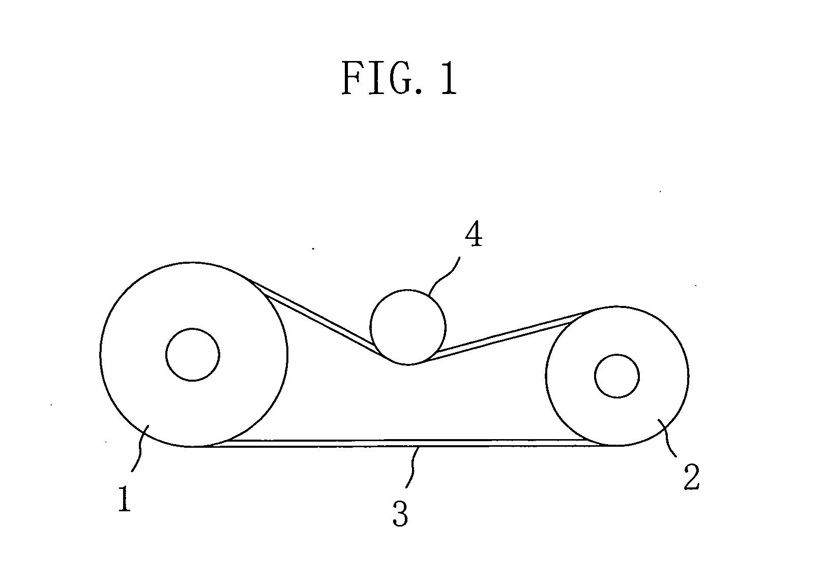
[0033]FIG. 1 shows a belt power transmission device according to the embodiment of the present invention. As shown in FIG. 1, the belt power transmission device includes: a driving pulley 1 (flat pulley); a driven pulley 2 (flat pulley); a flat belt 3 wound around both the pulleys 1 and 2; and a pulley 4 pressed against the flat belt 3.

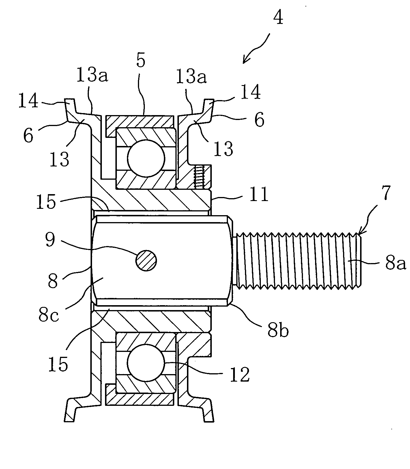
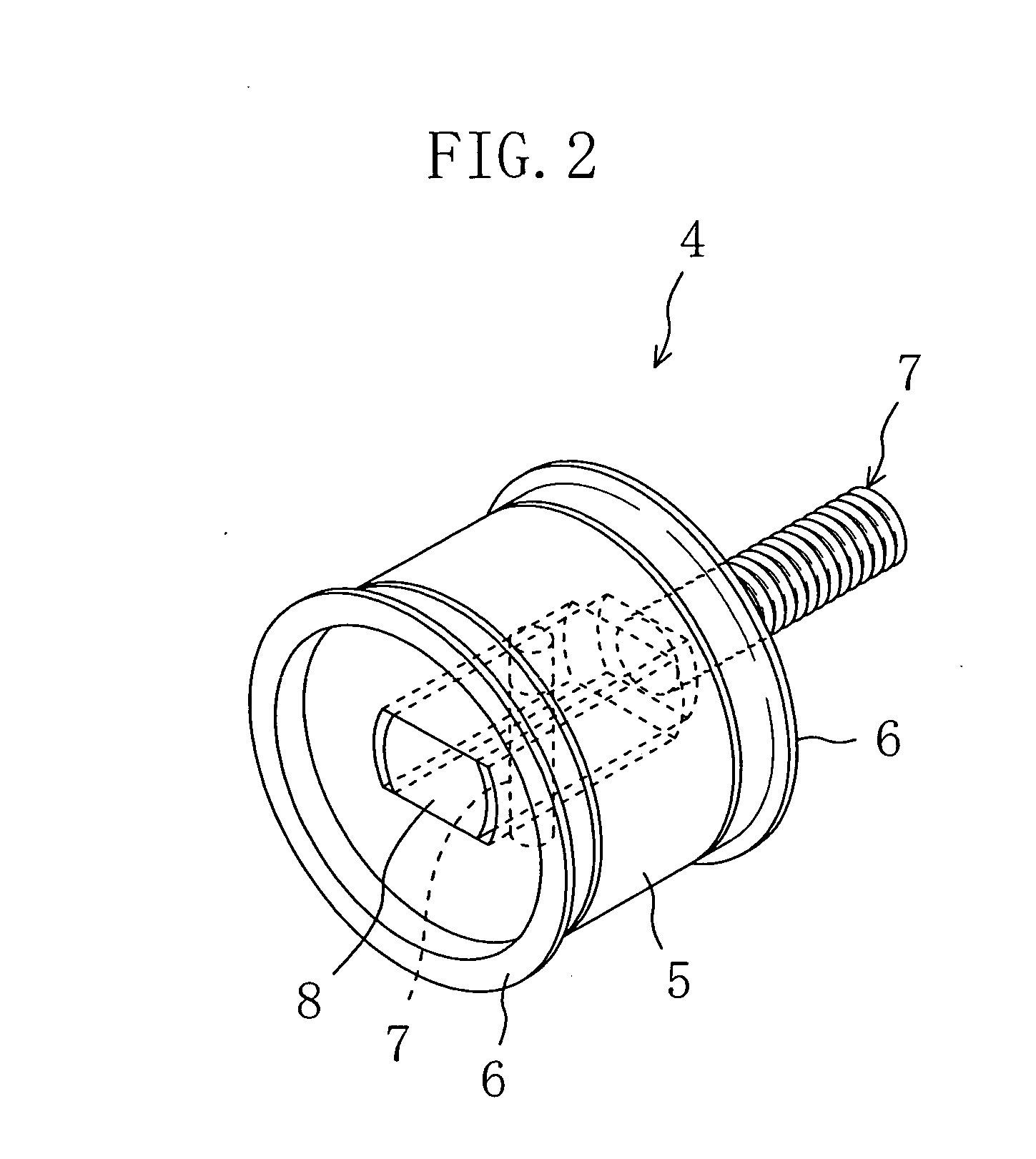
[0034] As shown in FIG. 2, the pulley 4 includes: a pulley body 5 around which the flat belt 3 is wound; power transmission members 6, 6 located at both sides of the pulley body 5; and a supporting means 7 for swingably supporting the pulley body 5 and the power transmission members 6, 6. The supporting means 7 includes a supporting rod 8 and a pin 9.

[0035] As shown in FIG. 3, the pulley body 5 is rotatably supported to a tubular shaft member 11 via a bearing 12. One of the power transmission members 6 is formed integrally with the ...


PUM


Abstract

A pulley body 5 is provided at its both sides with power transmission members 6, 6. When a flat belt 3 becomes misaligned relative to the center of the pulley body 5 and comes into contact with one of the power transmission members 6, a running force of the flat belt 3 is utilized to displace the pulley body 5 diagonally relative to the flat belt 3, thus producing a force for returning the flat belt 3 to its original state.

Description

BACKGROUND OF THE INVENTION [0001] (1) Field of the Invention [0002] The present invention relates to pulleys for power transmission belts, and belt power transmission devices. [0003] (2) Background Art [0004] In a power transmission device that uses a flat belt, the flat belt might zigzag during running, or might cause side tracking toward one side of a pulley. This is because, compared with other power transmission belts, a flat belt is susceptible to changes in components of a power transmission device, such as deviation of a pulley shaft from its proper position, deflection of the pulley shaft caused by a variation in shaft load, and wobbling of a pulley. If such zigzagging or side tracking occurs, a flat belt comes into contact with a flange of a flat pulley to scuff a side face of the flat belt or fray a cord. [0005] As the measures to prevent such a problem, in a known power transmission device, a crown (i.e., a crowned curved surface) is formed at a periphery of a flat pulle...

Claims


Application Information

Patent Timeline
Patent Type & Authority Applications(United States)
IPC IPC(8): F16H7/08F16H7/18F16H55/36F16H55/38
CPCF16H7/18F16H2055/363F16H2007/0865F16H55/36
Inventor MIYATA, HIROFUMINISHIKAWA, SHINICHIRO
Owner BANDO CHEM IND LTD
Why Eureka
Try Eureka