Vehicle obstacle detecting device

a detection device and vehicle technology, applied in the direction of pedestrian/occupant safety arrangement, using reradiation, instruments, etc., can solve the problems of limited freedom regarding the mounting position and the mounting direction of sensors (e.g., radars and/or cameras) with respect to the vehicle, and conventional systems are not arranged to positively utilize information regarding the blind, so as to improve detection reliability

Active Publication Date: 2005-01-20
NISSAN MOTOR CO LTD
View PDF6 Cites 67 Cited by
  • Summary
  • Abstract
  • Description
  • Claims
  • Application Information

AI Technical Summary

Benefits of technology

[0006] In the conventional technology disclosed in the above mentioned reference and in other such conventional systems, the detection reliability is improved by detecting the obstacle using a plurality of radars and / or cameras. However, in these conventional systems, the degree of freedom regarding the mounting position and the mounting direction of the sensors (e.g., radars and / or cameras) with respect to the vehicle is extremely limited because arrangements in which the sensing scopes of the radars and / or cameras overlap are limited.
[0007] Moreover, many of the conventional systems emphasize arranging the sensors such that there is basically no blind spot. On the other hand, there has been a demand for the ability to check the surroundings of the vehicle using as few sensors as possible depending on a system. However, in such conventional systems, as in the case of the technology disclosed in the above mentioned reference, several sensors are used in order to improve the detection reliability. In other words, the conventional systems are not arranged to positively utilize information regarding the blind spot of the sensors.
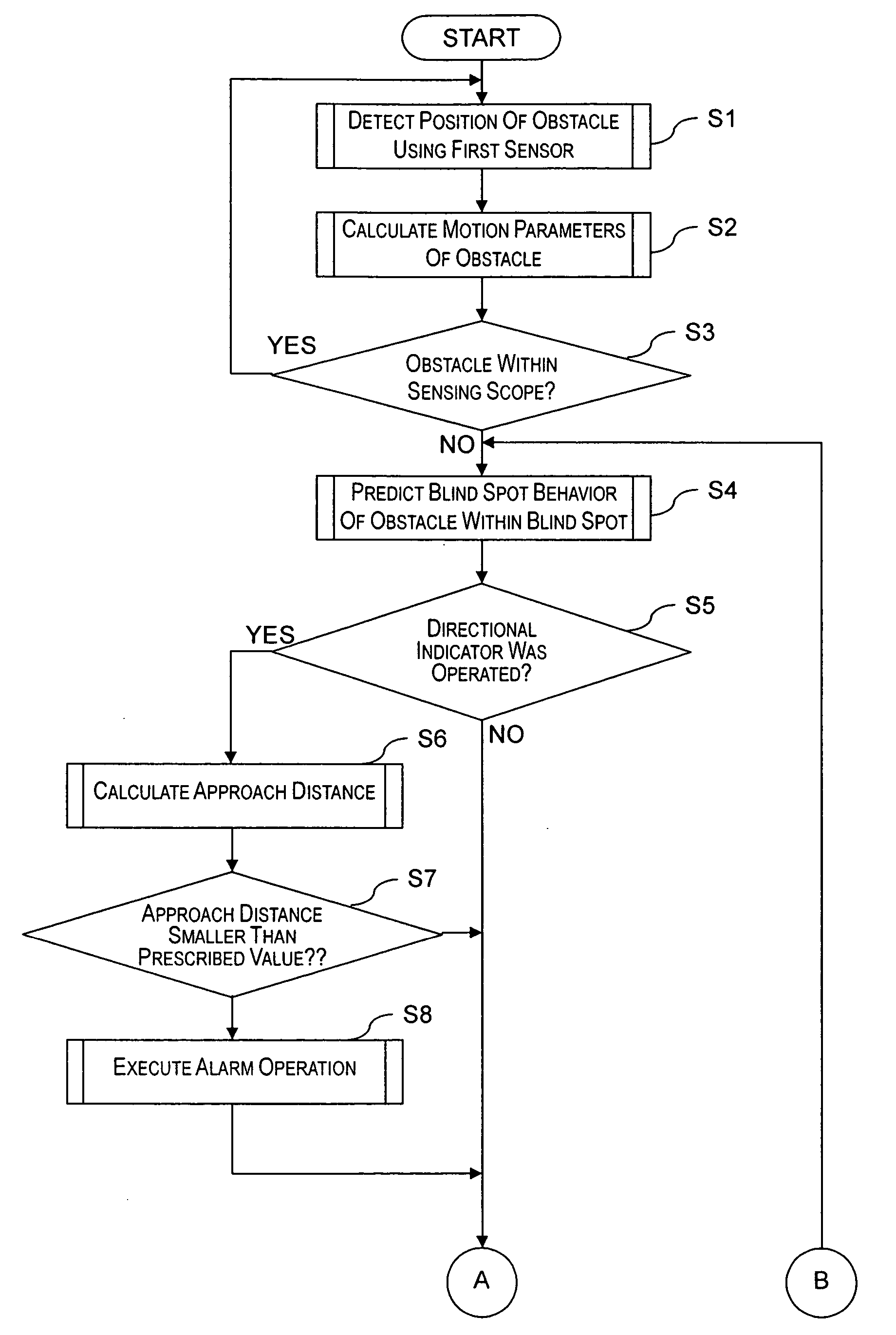
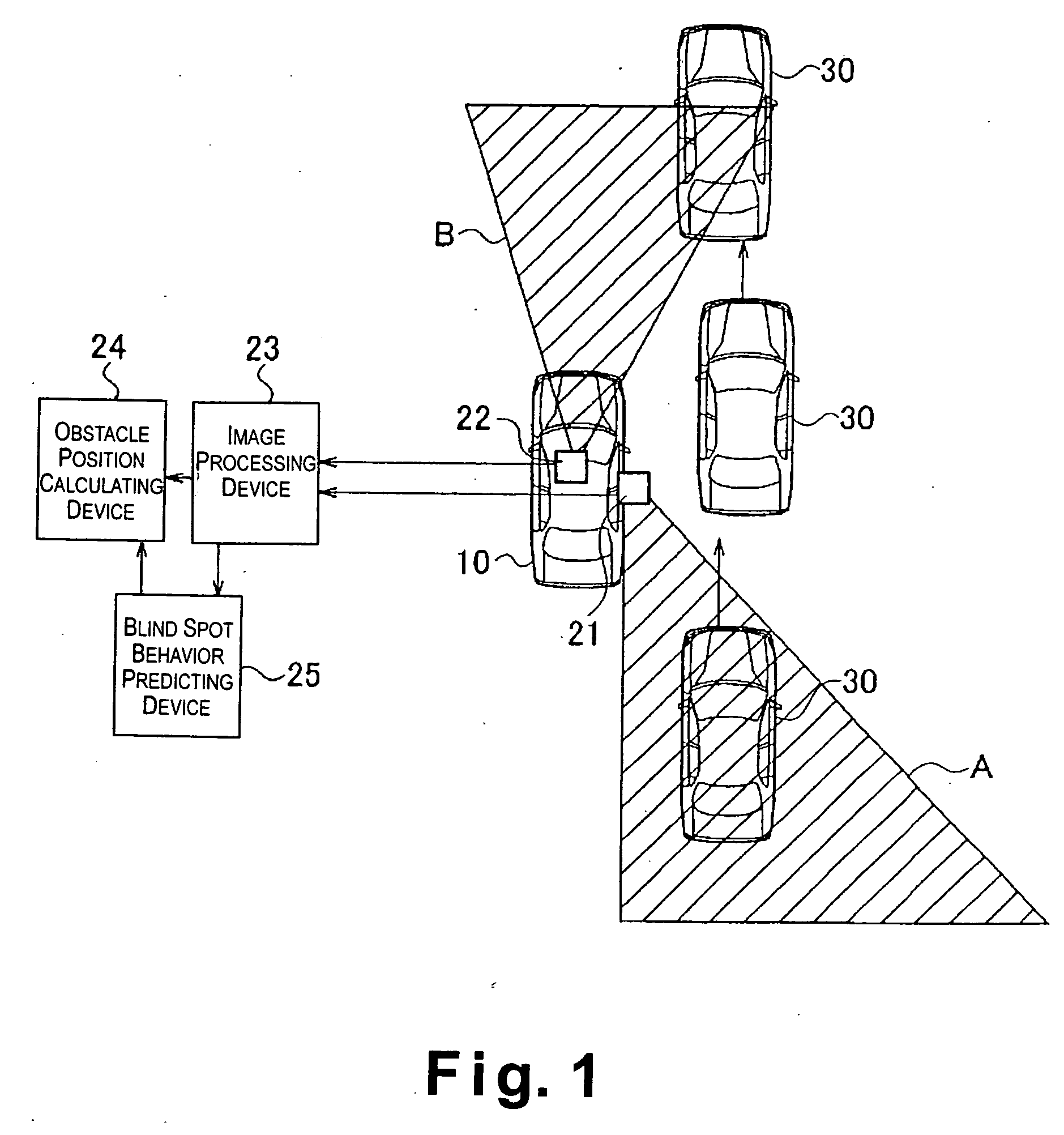
[0008] The present invention was conceived in view of the above mentioned problems in the conventional technologies. Thus, one of the objects of the present invention is to provide a vehicle obstacle detecting device that can effectively utilize information detected by a plurality of sensors to appropriately handle situations in which an obstacle exists in a blind spot of the sensors and improve the safety of the vehicle.

Problems solved by technology

However, in these conventional systems, the degree of freedom regarding the mounting position and the mounting direction of the sensors (e.g., radars and / or cameras) with respect to the vehicle is extremely limited because arrangements in which the sensing scopes of the radars and / or cameras overlap are limited.
In other words, the conventional systems are not arranged to positively utilize information regarding the blind spot of the sensors.

Method used


Image

  • Vehicle obstacle detecting device
  • Vehicle obstacle detecting device
  • Vehicle obstacle detecting device

Examples


second embodiment

[0072] Referring now to FIGS. 6-7, a vehicle obstacle detecting device in accordance with a second embodiment will now be explained. In view of the similarity between the first and second embodiments, the parts of the second embodiment that are identical to the parts of the first embodiment will be given the same reference numerals and step numbers as the parts of the first embodiment. Moreover, the descriptions of the parts of the second embodiment that are identical to the parts of the first embodiment may be omitted for the sake of brevity.

[0073] Basically, the second embodiment of the present invention is identical to the first embodiment, except that the adjustment of the prediction parameter is prohibited when the difference between the predicted blind spot behavior and the actual behavior of the obstacle is extremely large, e.g., larger than a prescribed value. Since the other configurations of the vehicle obstacle detecting device of the second embodiment is identical to th...

third embodiment

[0083] Referring now to FIGS. 8 and 9, a vehicle obstacle detecting device in accordance with a third embodiment will now be explained. In view of the similarity between the first, second and third embodiments, the parts of the third embodiment that are identical to the parts of the first and second embodiments will be given the same reference numerals as the parts of the first and second embodiments. Moreover, the descriptions of the parts of the third embodiment that are identical to the parts of the first and second embodiments may be omitted for the sake of brevity.

[0084] The third embodiment of the present invention is basically identical to the first embodiment of the present invention, except that the vehicle obstacle detecting device of the third embodiment is further configured to determine whether large discrepancies between the predicted blind spot behavior and the actual behavior of the obstacle are occurring on a frequent basis, and diagnose whether a system abnormalit...


PUM


Abstract

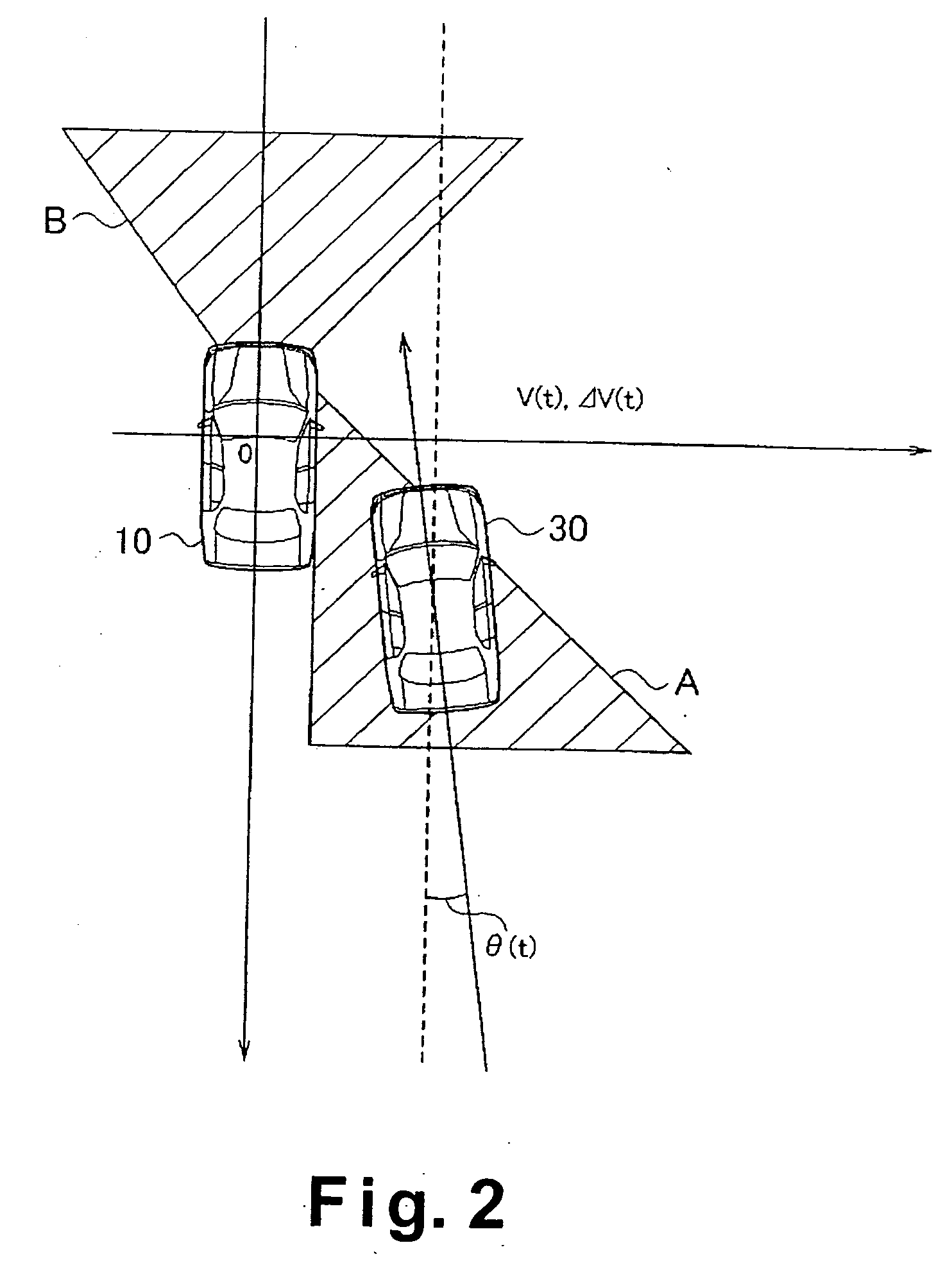
The vehicle obstacle detecting device improves safety of the vehicle by utilizing information detected by a plurality of sensors to appropriately handle situations in which an obstacle exists in a blind spot of the sensors. The vehicle obstacle detecting device includes at least first and second sensors arranged such that sensing scopes of the first and second sensors do not substantially overlap. The vehicle obstacle detecting device is configured to observe the behavior of an obstacle existing within the sensing scope of one of the first and second sensors and predict the blind spot behavior of the obstacle in a blind spot between the sensing scopes of the first and second sensors based on the observed behavior of the obstacle. Thus, the vehicle obstacle detecting device is configured to predict the existence of an obstacle in the blind spot where the first and second sensors cannot actually detect the obstacle.

Description

BACKGROUND OF THE INVENTION [0001] 1. Field of the Invention [0002] The present invention relates to a vehicle obstacle detecting device adapted to be mounted on a vehicle. More specifically, the present invention relates to a vehicle obstacle detecting device configured to detect an obstacle in the vicinity of the vehicle by using a plurality of sensors whose sensing scopes do not overlap one another. [0003] 2. Background Information [0004] There have been known technologies for detecting obstacles in the vicinity of a moving vehicle in order to improve the driving safety of the vehicle. For example, Japanese Laid-Open Patent Publication No. 10-31799 discloses an automatic travel control device that detects the position of a vehicle with respect to a traveling road or lane and controls the steering of the vehicle. In particular, the automatic travel control device disclosed in the above mentioned reference has a radar and a CCD (charged coupled device) or other cameras mounted onto...

Claims


Application Information

Patent Timeline
Patent Type & Authority Applications(United States)
IPC IPC(8): B60R21/00G01S13/931G08G1/16
CPCG01S13/931G08G1/16G01S2013/9332G08G1/166G08G1/167G01S2013/9315
Inventor TAKAHASHI, HIROSHI
Owner NISSAN MOTOR CO LTD
Why Eureka
Try Eureka