
Protective sheild for a tool

a protective sheath and tool technology, applied in the field of protective devices, can solve the problems of debris coming into contact with the operator, significant friction, and debris emitted during tooling operations, and achieve the effect of preventing injury from debris

Inactive Publication Date: 2005-01-20
VIDAL ROBERT J
View PDF13 Cites 38 Cited by
  • Summary
  • Abstract
  • Description
  • Claims
  • Application Information

AI Technical Summary

Benefits of technology

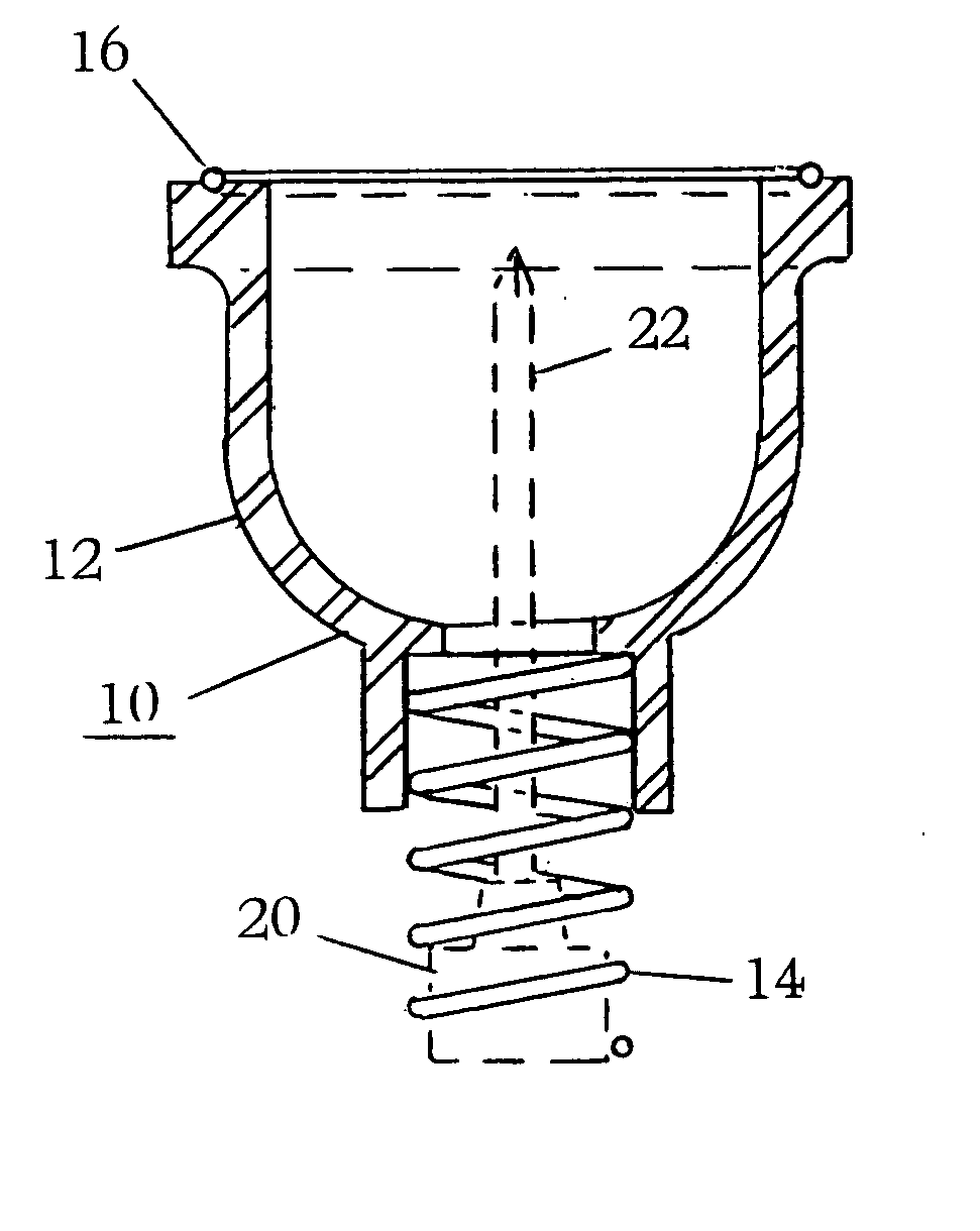
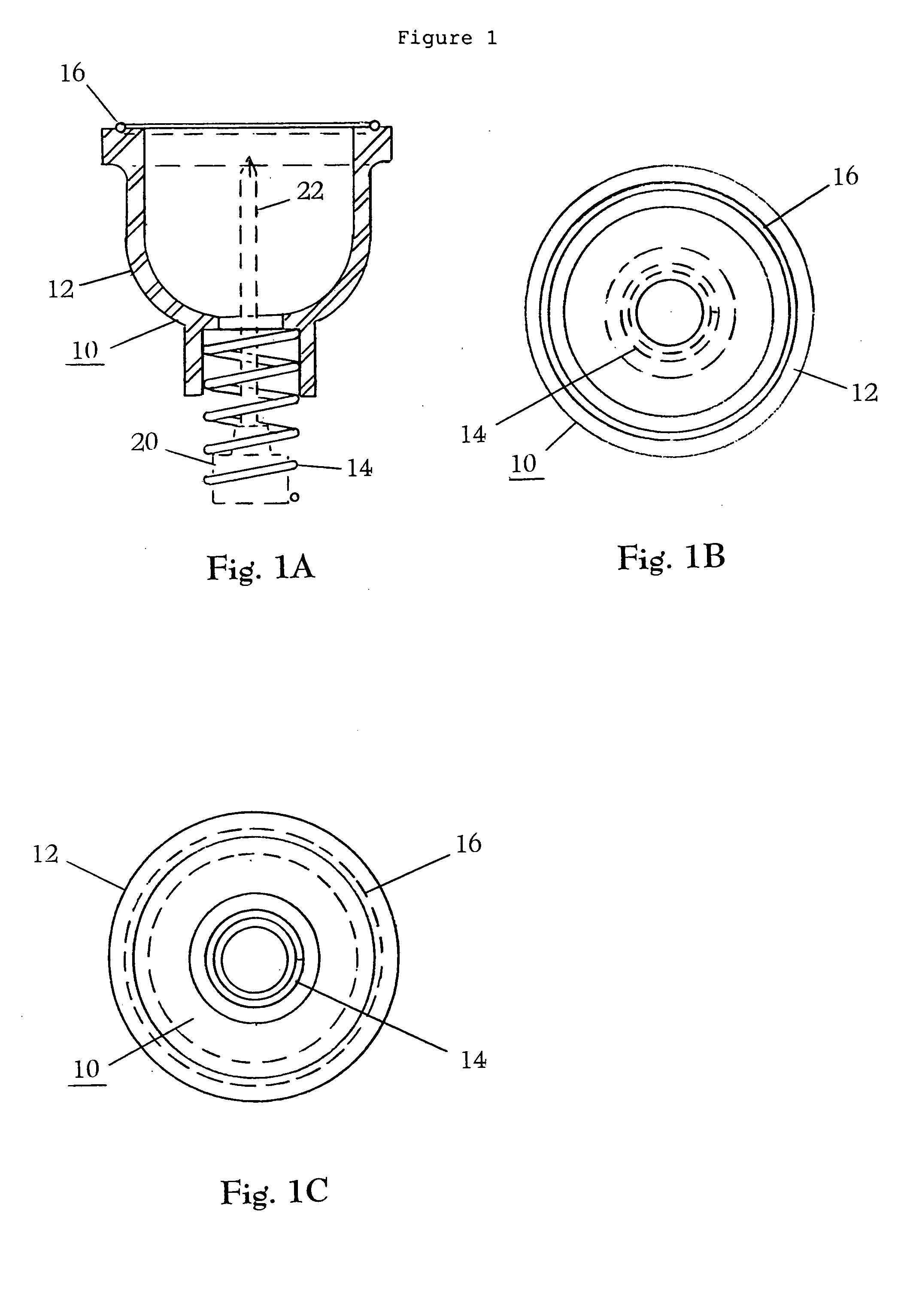
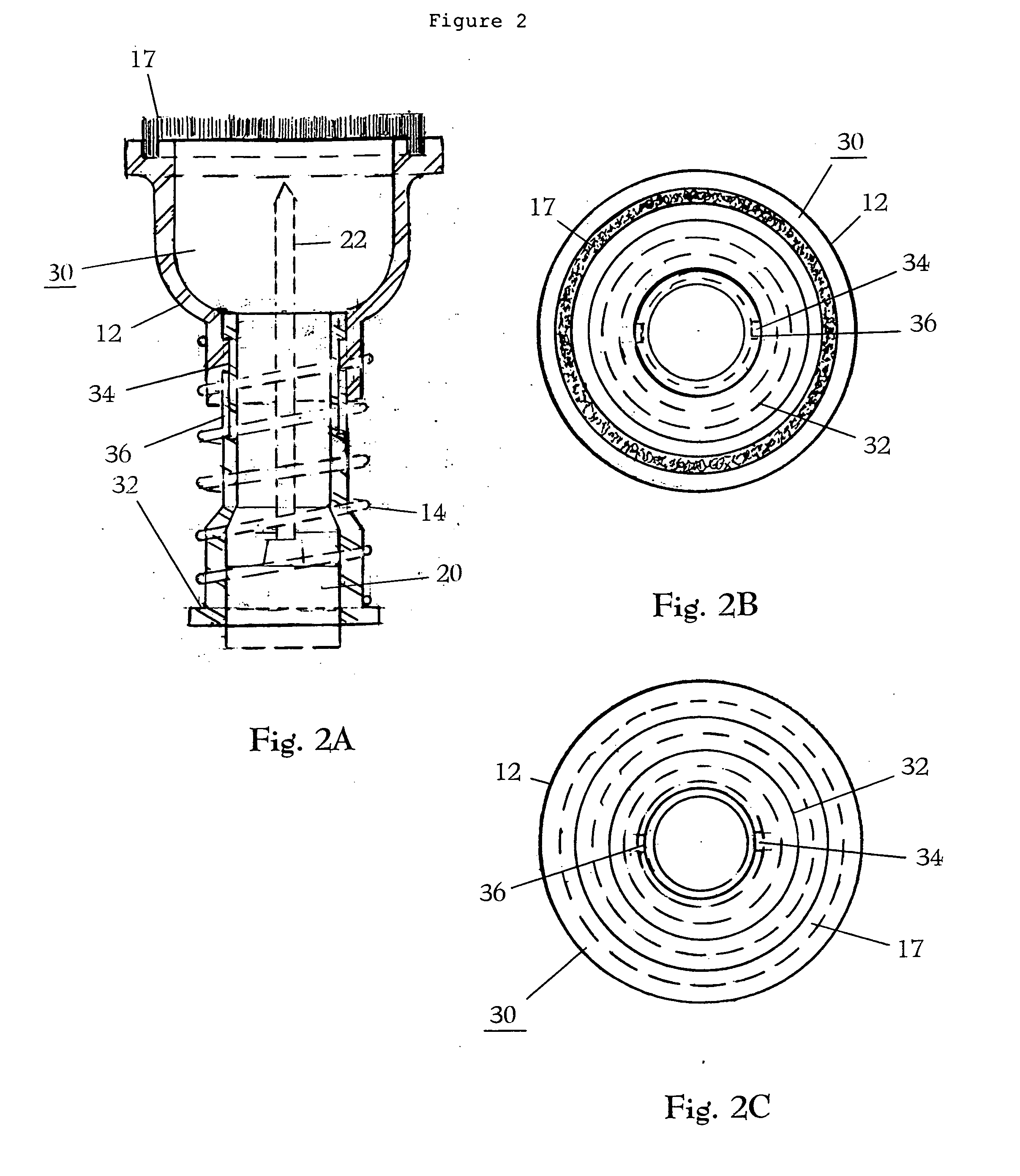
[0006] In one embodiment the cylindrical-shaped housing may be provided in a variety of shapes including conical cylinder shaped, semi-elliptical cylinder shaped, semi-oval cylinder shaped, semi-elliptical conical shaped or semi-oval conical shaped. It may also be prepared from a variety of materials having particular desirable characteristics such as strength and durability, heat and impact resistance, and transparency. Preferably the cylindrical-shaped housing is cup shaped and made of a impact and heat resistant, transparent material.
[0015] In yet another aspect of the present invention a method for preventing injury from debris resulting from the operation of a drilling or cutting tool is provided comprising the steps of affixing a protective shield onto a drilling or cutting tool and operating the drilling or cutting tool.

Problems solved by technology

One disadvantage of using these tools is the debris emitted during the tooling operations.
When working with high-density materials such as for example metal, stone or ceramics, injury can result when this debris comes in contact with the operator.
This action of cutting or drilling creates a substantial amount of friction, which increases the temperature at the interface between the cutting edge and the material.
Consequently, injury can result if this debris impacts the user or others in the immediate area.
Correspondingly, items in the immediate area may also be damaged if they come in contact with this debris.
However, safety glasses cannot protect against searing hot debris that enters from above and along the sides where the safety glasses do not fit flush against the face.
In addition, collar and sleeve openings that are not securely sealed can provide access to this potentially dangerous debris.
Finally, clothing may not protect the user from high velocity impacts, which can penetrate the cloth, and while certain clothing may be resistant to high impact, it may still scorch or potentially catch fire.

Method used


Image

  • Protective sheild for a tool
  • Protective sheild for a tool
  • Protective sheild for a tool

Examples


Embodiment Construction

[0020] Unless defined otherwise, all terms used herein have the same meaning as are commonly understood by one of skill in the art to which this invention belongs. All patents, patent applications and publications referred to throughout the disclosure herein are incorporated by reference in their entirety. In the event that there is a plurality of definitions for a term herein, those in this section prevail.

[0021] The term “debris” as used herein refers to particles emitted from the surface of a working material as a result of tooling or machining operations. Such debris may include for example shavings, burrs or chips.

[0022] The terms “operating”, “operation” or “operations” as used herein refers to the act of using a tool to alter the character of a working material such as by drilling a hole, cutting into a desired shape, or driving a screw into the surface or the like by methods known to one skilled in the art.

[0023] The term “working materials” as used herein refers to a var...


PUM

PropertyMeasurementUnit
Electrical resistanceaaaaaaaaaa
Transparencyaaaaaaaaaa
Lightaaaaaaaaaa

Abstract

A protective shield for a drilling or cutting tool having a cylindrical-shaped housing that has a front end and a back end, the front end able to fit flush against a working surface; and a spring having a first end and a second end, the first end able to receive the back end of the cylindrical-shaped housing and the second end able to receive a drilling or cutting tool chuck; the cylindrical-shaped housing able to receive debris from the drilling or cutting tool operation.

Description

TECHNICAL FIELD [0001] The present invention relates to protective devices used in conjunction with tools for drilling or cutting. In particular, a device for shielding the operator from debris emitted from drilling or machining operations in high-density materials such as stone or metal. BACKGROUND OF THE INVENTION [0002] A wide variety of cutting and drilling tools are used in both the commercial and private sectors worldwide for a variety of purposes including construction, fabrication and manufacturing. One disadvantage of using these tools is the debris emitted during the tooling operations. When working with high-density materials such as for example metal, stone or ceramics, injury can result when this debris comes in contact with the operator. Drilling or cutting operations in high-density materials generally requires a sharp cutting edge moving at high speed to effect the desired result. Such speeds are usually achieved with power tools. This action of cutting or drilling c...

Claims


Application Information

Patent Timeline
IPC IPC(8): B23B47/00B23B47/34B23Q11/00
CPCB23Q11/0064Y10T408/50Y10T408/21Y10T408/03
Inventor VIDAL, ROBERT J.
Owner VIDAL ROBERT J
Learn More