Wall anchor for a screw, and assembly constituted by such a wall anchor and screw

a technology of wall anchors and screws, which is applied in the direction of fastening means, dowels, mechanical devices, etc., can solve the problems of inability to use walls, create constraints, and additional manufacturing and storage costs, and avoid the risk of accidental spreading of teeth

Inactive Publication Date: 2005-01-20
BLACK & DECKER INC
View PDF1 Cites 9 Cited by
  • Summary
  • Abstract
  • Description
  • Claims
  • Application Information

AI Technical Summary

Benefits of technology

[0011] To this end, according to a preferred embodiment of a wall anchor according to the invention, at least one of the free sides of each tooth, turned in a specific circumferential direction, is in the shape of a cutting edge. This makes it possible to drill the receiving hole for the wall anchor by rotation of the latter about its axis in the aforesaid circumferential direction.
[0012] According to an even more preferred embodiment, the two free sides of each tooth are in the respective shape of a cutting edge. This makes it possible to carry out drilling by rotation of the wall anchor in one direction or the other.
[0013] The head shaft has an indentation to enable the appropriate rotational movement to be imparted to the wall anchor. A screwdriver is inserted into the indentation and rotated thereby making it possible to carry out drilling without having to engage a screw in the wall anchor.
[0014] It is also possible, of course, to act for this purpose on the wall anchor by acting on the transverse head of a screw. The screw rod is engaged with the internal thread of the screw nut shaft. The head bears against

Problems solved by technology

The presence of the point which extends the screw rod of the screw beyond the anchor constitutes a drawback in so far as it is necessary.
Another drawback of the necessary presence of the guide point in the extension of the screw rod of th

Method used


Image

  • Wall anchor for a screw, and assembly constituted by such a wall anchor and screw
  • Wall anchor for a screw, and assembly constituted by such a wall anchor and screw
  • Wall anchor for a screw, and assembly constituted by such a wall anchor and screw

Examples


Embodiment Construction

[0033] The following description of the preferred embodiment(s) is merely exemplary in nature and is in no way intended to limit the invention, its application, or uses.

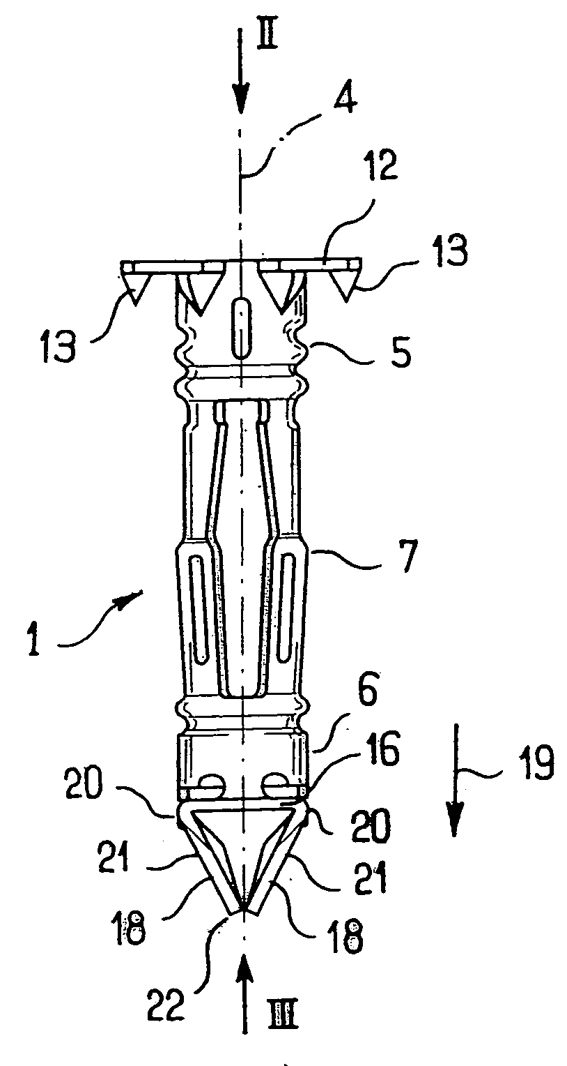
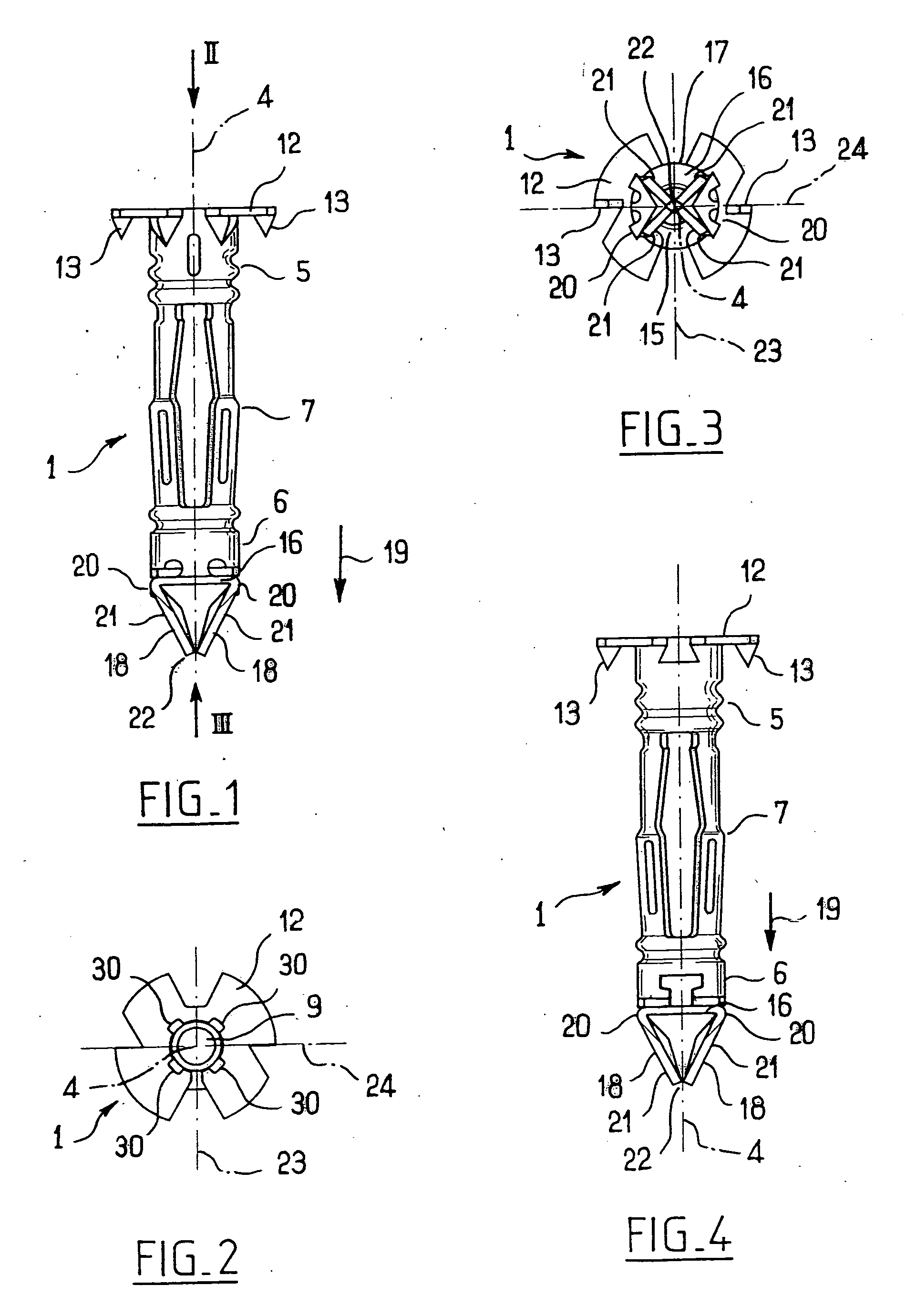
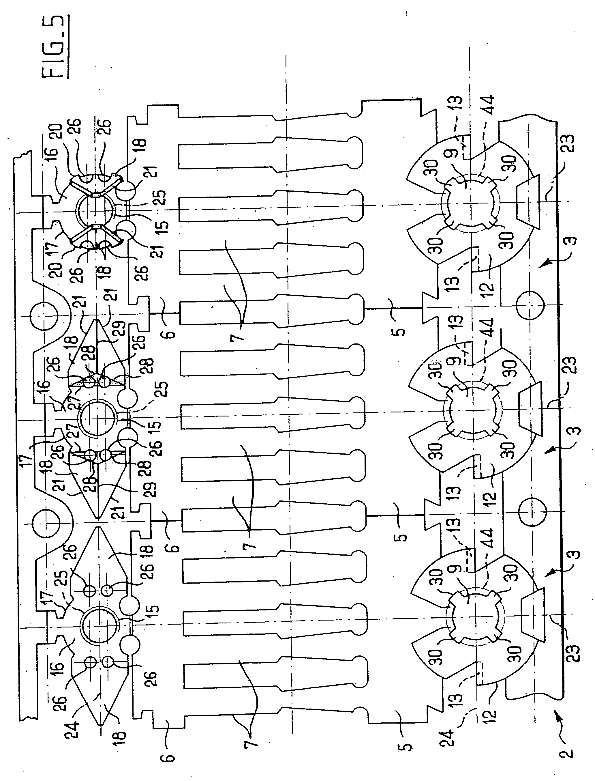
[0034] Reference will be made first to FIGS. 1 to 4, where a wall anchor 1 according to the invention is illustrated. The wall anchor 1 is advantageously produced in one piece by pressing, winding and folding a metal strip 2. A section of the metal strip is illustrated in FIG. 5. Three consecutive states characterize the production of a wall anchor according to the invention from such a strip 2 of a blank 3 for a wall anchor 1. For reasons of simplicity, the same numerical references will be used to designate the different parts of the wall anchor 1 according to the invention and the corresponding parts of the blank 3.

[0035] The wall anchor 1 defines a longitudinal axis 4 of general symmetry. A head shaft 5 and a screw nut shaft 6 are each in the form of a tubular sleeve of revolution about the axis 4. The head 5 a...


PUM


Abstract

A wall anchor (1) has a head shaft (5) and a screw nut shaft (6) on the same longitudinal axis (4), connected to each other by a plurality of approximately longitudinal small bars (7). The bars (7) are plastically flexible in a direction away from the axis (4). The screw nut shaft (6) is equipped with teeth (18) of generally triangular shape. The teeth (18) form a longitudinal projection with respect thereto and converge on the axis (4) to define a point (22) to perforate or drill a partition (8).

Description

CROSS-REFERENCE TO RELATED APPLICATIONS [0001] This application claims priority to French Patent Application No. 0305032 filed Apr. 24, 2003, which application is herein expressly incorporated by reference. FIELD OF THE INVENTION [0002] The present invention relates to a wall anchor for a screw, of the type defining a longitudinal axis and includes teeth to enable insertion into a partition. BACKGROUND OF THE INVENTION [0003] A wall anchor constituted essentially by upsetting and bending a single metal strip, is described in FR-B 2 640 704 and in EP-B 0 378 907. An embodiment in which it is intended to be used, in the manner of a wood bit of the type known by the name “center bit”, to drill a partition in which it is to be anchored. It is driven by rotation on itself about its axis with respect to the partition. For example a screwdriver, acting on a head of the screw, the screw rod of which is screwed into the screw nut shaft and the head is positioned so as to bear longitudinally ...

Claims


Application Information

Patent Timeline
IPC IPC(8): F16B13/00F16B13/06F16B13/12
CPCF16B13/001F16B13/124F16B13/061F16B13/002
Inventor ANQUETIN, ROBERT
Owner BLACK & DECKER INC
Why Eureka
Try Eureka