Dental implant system

Active Publication Date: 2005-01-20
NOBEL BIOCARE SERVICES AG
View PDF75 Cites 77 Cited by
  • Summary
  • Abstract
  • Description
  • Claims
  • Application Information

AI Technical Summary

Problems solved by technology

This bone loss is undesirable both aesthetically and structurally.
However, due to the irregular configuration of the alveolar crest, a flat interface makes it difficult to conform to a proper biological width in all 360 degrees around the implan

Method used


Image

  • Dental implant system
  • Dental implant system
  • Dental implant system

Examples


Embodiment Construction

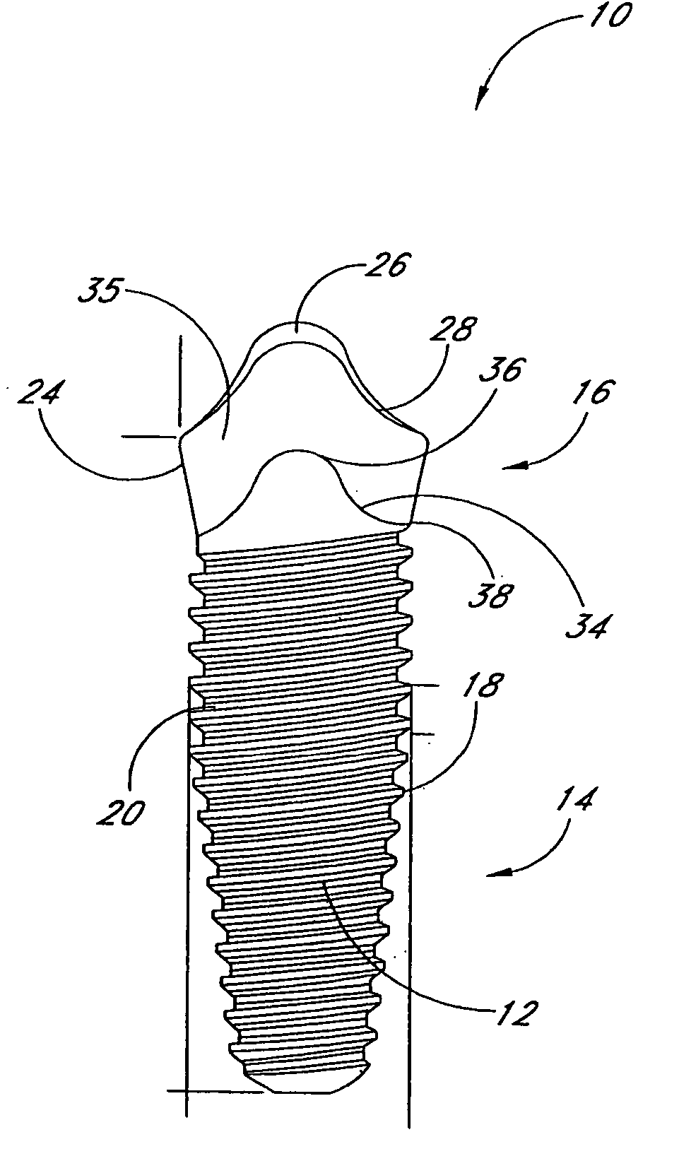
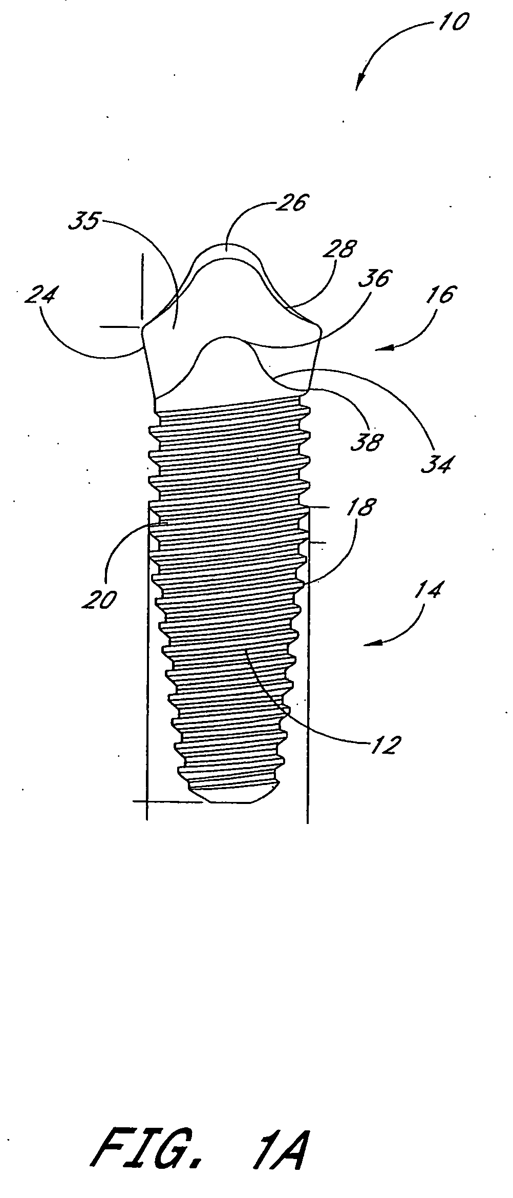
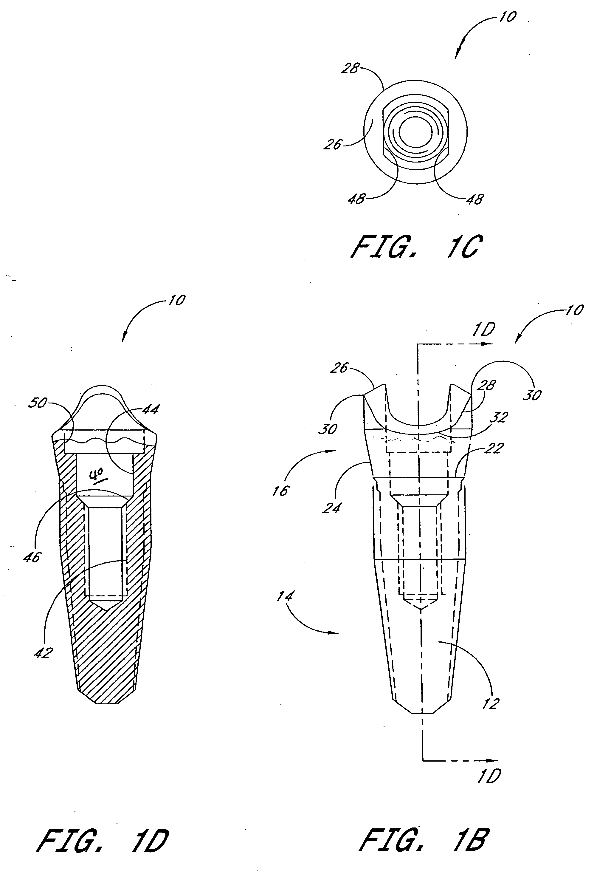
[0071] FIGS. 1A-D illustrate an exemplary embodiment of a dental implant 10. In this embodiment, the implant 10 comprises an implant body 12, which preferably includes a lower portion 14 and a collar 16. The implant 10 may be made of titanium although other materials may also be used. The lower portion 14 is preferably tapered and includes threads 18 that match preformed threads made along the inner surface of a bore in the patient's jawbone (not shown). However, it should be appreciated that the lower portion 14 can be configured so as to be self-tapping or unthreaded. It should also bee appreciated that although the illustrated lower portion 14 is tapered or conical it may also be substantially cylindrical.

[0072] In the illustrated embodiment, the lower portion 14 preferably has a bone apposition surface 20, which is configured to promote osseointegration. In one embodiment, the bone apposition surface 20 increases the surface area of the lower portion 12. For example, the bone a...


PUM


Abstract

A dental implant assembly for supporting a dental prosthesis. The assembly comprises a dental implant and an abutment. The dental implant comprises a body portion, a collar portion and a central bore. The body portion is located at a distal end of the dental implant and is configured to lie at least substantially below a crest of a patient's jawbone. The collar portion is located at a proximal end of the dental implant and forms an abutment mating surface which defines an outer edge that has a generally scalloped shape. The central bore extends through the collar portion and into the implant body portion. The central bore includes a threaded portion and a post portion. The abutment comprises a post configured to fit within the post portion of the central bore and an implant mating surface that is configured to mate with the abutment mating surface of the dental implant.

Description

PRIORITY INFORMATION [0001] This application claims the priority benefit under 35 U.S.C. §119(e) of Provisional Application 60 / 471,036 filed May 16, 2003 entitled “Dental Implant System”, Provisional Application 60 / 472,234 filed May 21, 2003, and Provisional Application 60 / 479,530 filed Jun. 18, 2003, the entirety all of these applications are hereby incorporated by reference herein.BACKGROUND OF THE INVENTION [0002] 1. Field of the Invention [0003] The present invention relates generally to dental implants and, more particularly, to an improved dental implant system. [0004] 2. Description of the Related Art [0005] Implant dentistry involves the restoration of one or more teeth in a patient's mouth using artificial components. Such artificial components typically include a dental implant and a prosthetic tooth and / or a final abutment that is secured to the dental implant. Generally, the process for restoring a tooth is carried out in three stages. [0006] Stage I involves implanting ...

Claims


Application Information

Patent Timeline
IPC IPC(8): A61C8/00
CPCA61C8/0018A61C8/0022A61C8/005A61C8/0054A61C8/0086A61C8/0066A61C8/0069A61C8/0077A61C8/006
Inventor WOHRLE, PETER S.HOWLETT, CHARLES W.
Owner NOBEL BIOCARE SERVICES AG
Why Eureka
Try Eureka