Flexible fixture

a flexible fixture technology, applied in the direction of metal working machine components, metal working tools, metal working apparatuses, etc., can solve the problems of limiting the curvature of workpieces, and it is difficult to orient the vacuum cup normal to the surface of workpieces in order to be properly seated

Active Publication Date: 2005-01-27
PAR SYST INC
View PDF30 Cites 51 Cited by
  • Summary
  • Abstract
  • Description
  • Claims
  • Application Information

AI Technical Summary

Problems solved by technology

The grid pattern of the posts and the setting bridge may limit the extent of curvature that the workpieces can have.
However, for workpieces having high curvature, this may cause the loose coupling to drop under gravity, rendering it difficult to orient the vacuum cup normal to the surface of the workpiece in order to be properly seated.

Method used


Image

  • Flexible fixture
  • Flexible fixture
  • Flexible fixture

Examples


Embodiment Construction

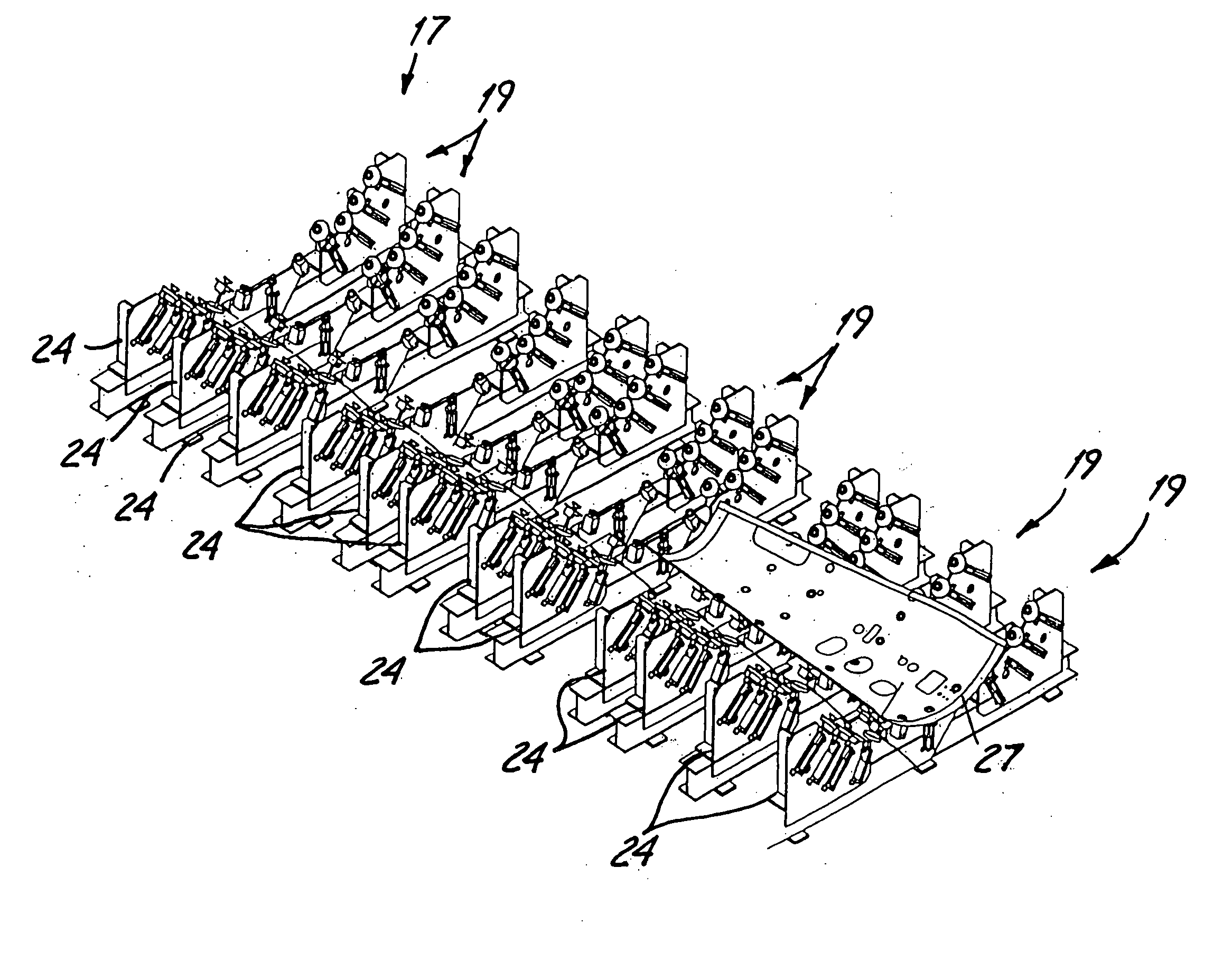
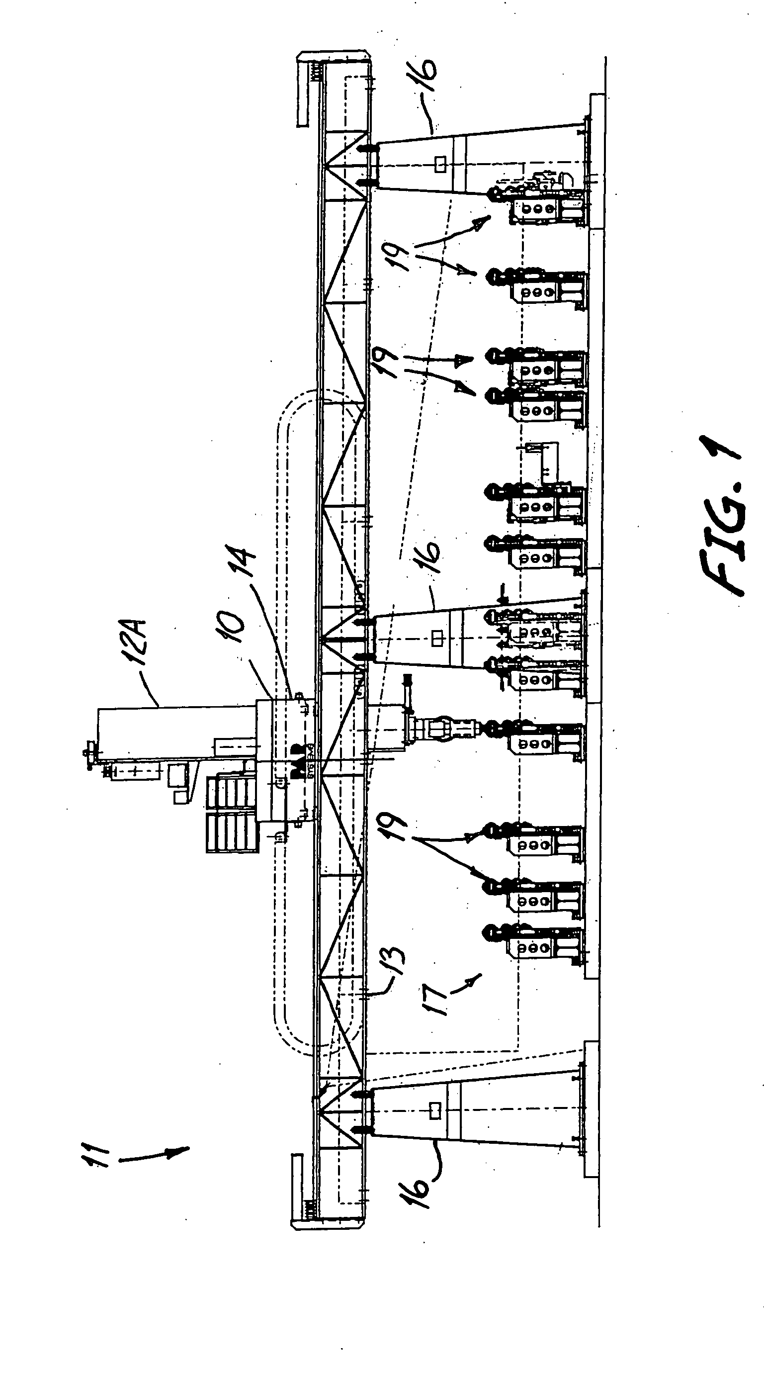
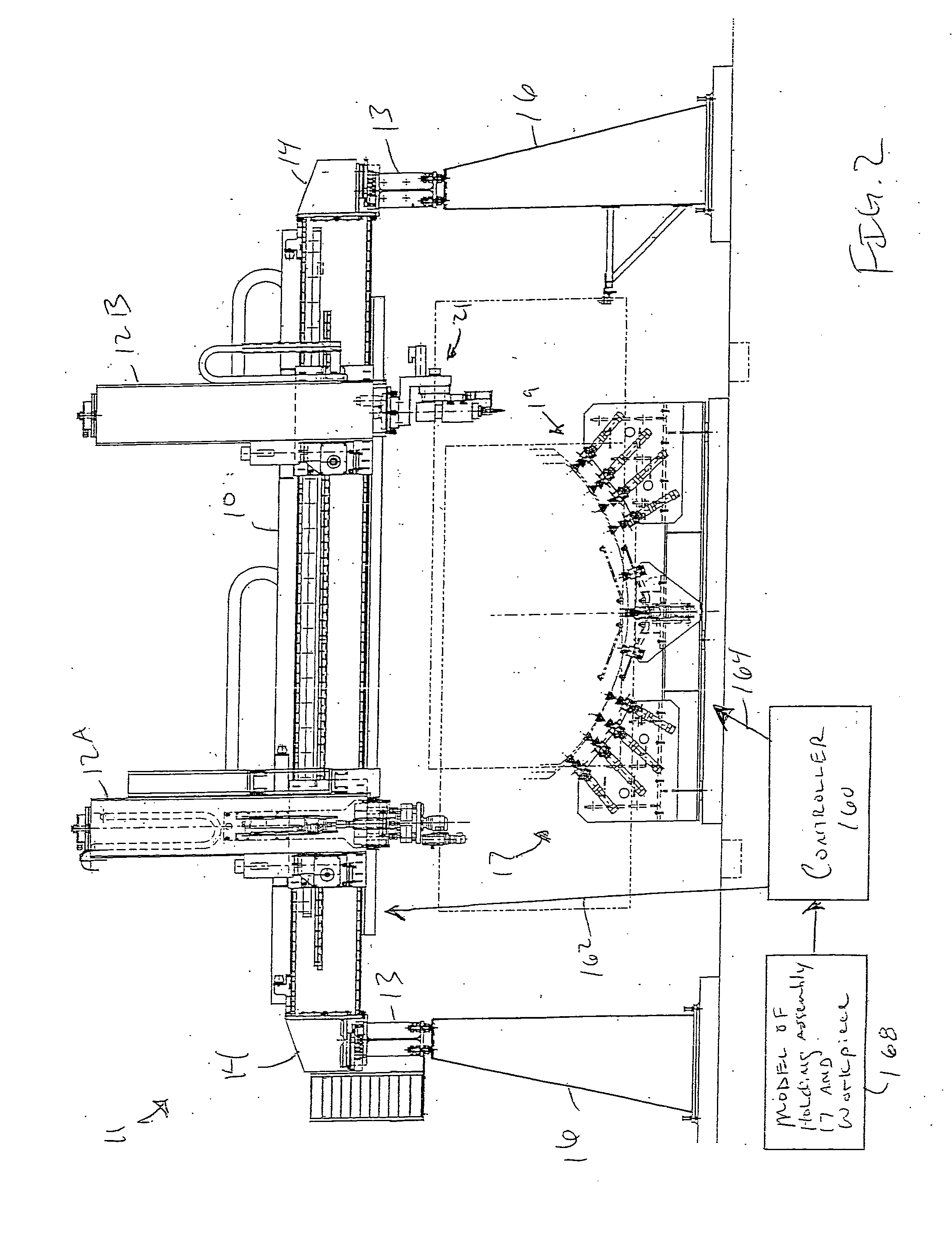
[0024] Referring to FIGS. 1-2, a gantry or positioning system is illustrated at 11. The gantry system 11 includes a pair of space-apart rails 13. In the exemplary embodiment, rails 13 are elevated, being supported by supports 16. A bridge 10 spans between rails 13. Two trucks 14 are coupled to bridge 10 and further coupled to rails 13 in order to provide horizontal movement of bridge 10 in a direction parallel to the guide rails 13. Bridge 10 supports at least one mast 12A and 12B. In the embodiment illustrated, mast 12A is adapted to hold an end effector such as a laser cutting device for performing work on a workpiece supported by a holding assembly 17. Mast 12B is also adapted to hold an end effector, which can include for example, a drill for performing work on the workpiece, but as further explained below, can also hold an aligning fixture used to position and / or orient each of a plurality of support assemblies 19 comprising the holding assembly 17.

[0025] In the embodiment ill...


PUM

PropertyMeasurementUnit
curvatureaaaaaaaaaa
flexibleaaaaaaaaaa
vacuumaaaaaaaaaa

Abstract

The present invention relates to an aligning fixture having a support with a reference surface, an aligning member and an actuator. The actuator is mounted to the support and operably coupled to the aligning member. The actuator moves the aligning member selectively to a first position wherein the element to be aligned is spaced apart from the reference surface and to a second position where the element can engage the reference surface.

Description

CROSS REFERENCE TO RELATED APPLICATION [0001] The present application is based on and claims the benefit of U.S. provisional patent application Ser. No. 60 / 480,213, filed Jun. 20, 2003, the content of which is hereby incorporated by reference in its entirety.BACKGROUND OF THE INVENTION [0002] The present invention relates to fixtures for holding workpieces during machining, inspection or other operations performed thereon. In particular, aspects of the present invention relate to a fixture for holding large workpieces having surfaces of high curvature or other complex shapes. [0003] Holding fixtures for three dimensional workpieces are available from Modig Machine AB of Virserum, Sweden and CNA Manufacturing Systems, Inc. of Woodinville, Wash. These fixtures hold workpieces in a fixed position through an array of posts. Each of the posts are equipped with a flexible vacuum cup that when seated upon a portion of the surface of the workpiece forms a vacuum. When a vacuum is pulled in ...

Claims


Application Information

Patent Timeline
Patent Type & Authority Applications(United States)
IPC IPC(8): B23PB23Q3/00B23Q3/06B23Q7/00
CPCB23Q1/035B23Q3/062B23Q2230/002Y10T29/49902Y10T29/49998Y10T29/53052Y10T29/49895
Inventor STURM, ALBERT J. JR.RIECKENBERG, WESLEY J.WENIGER, RICHARD J.
Owner PAR SYST INC
Why Eureka
Try Eureka