Measuring arrangement to determine location of corners for a building foundation and a wooden base frame, and the use thereof

Inactive Publication Date: 2005-01-27
ARMSTRONG TIMOTHY D +1
View PDF17 Cites 48 Cited by
  • Summary
  • Abstract
  • Description
  • Claims
  • Application Information

AI Technical Summary

Benefits of technology

[0009] The object of the present invention is to simplify the above-described processes while improving accuracy and

Problems solved by technology

Further, only one worker is re

Method used


Image

  • Measuring arrangement to determine location of corners for a building foundation and a wooden base frame, and the use thereof
  • Measuring arrangement to determine location of corners for a building foundation and a wooden base frame, and the use thereof
  • Measuring arrangement to determine location of corners for a building foundation and a wooden base frame, and the use thereof

Examples


Embodiment Construction

[0037] Please note that the same reference numerals have been used in some of the figures for similar components of different embodiments of the present invention.

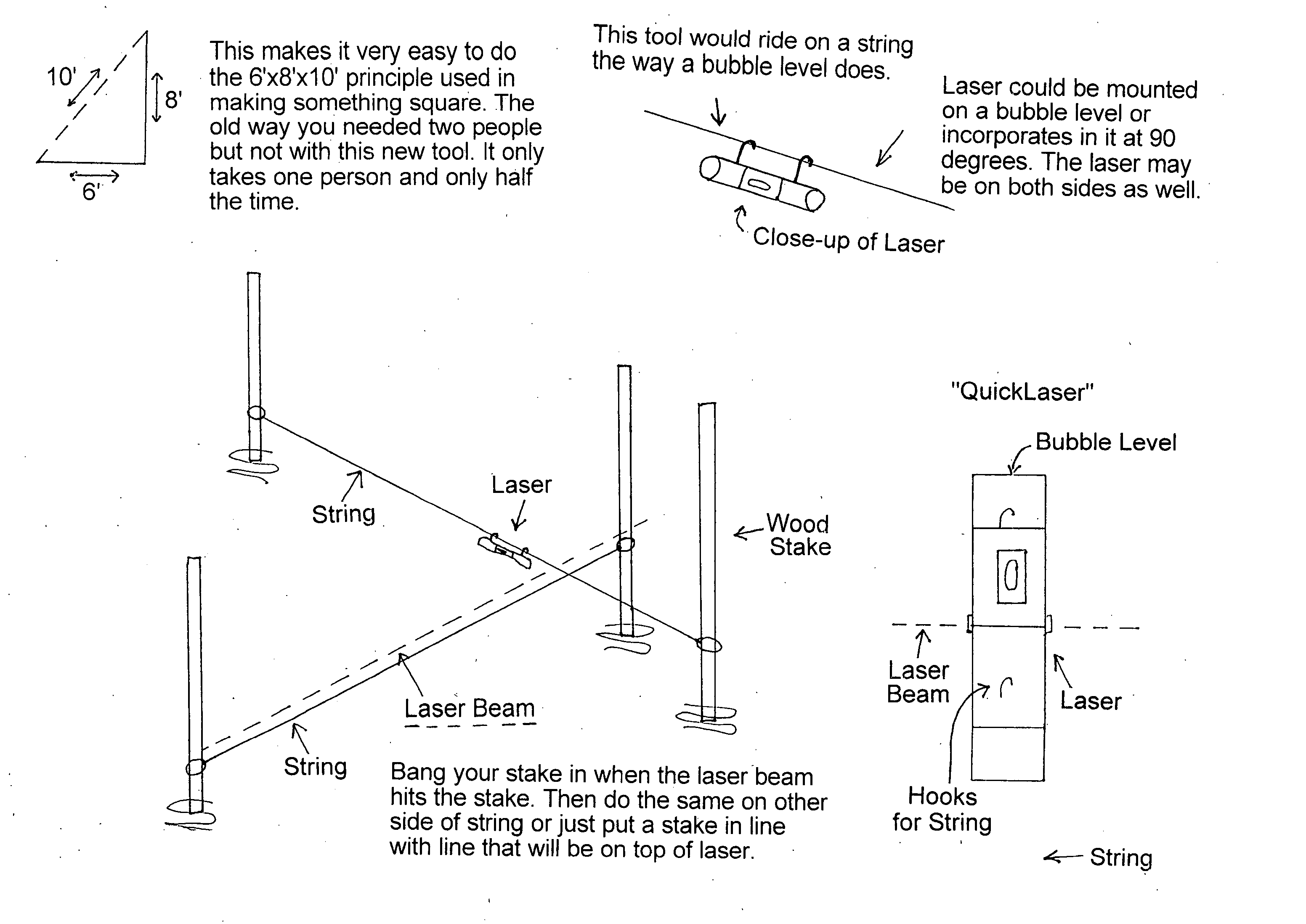
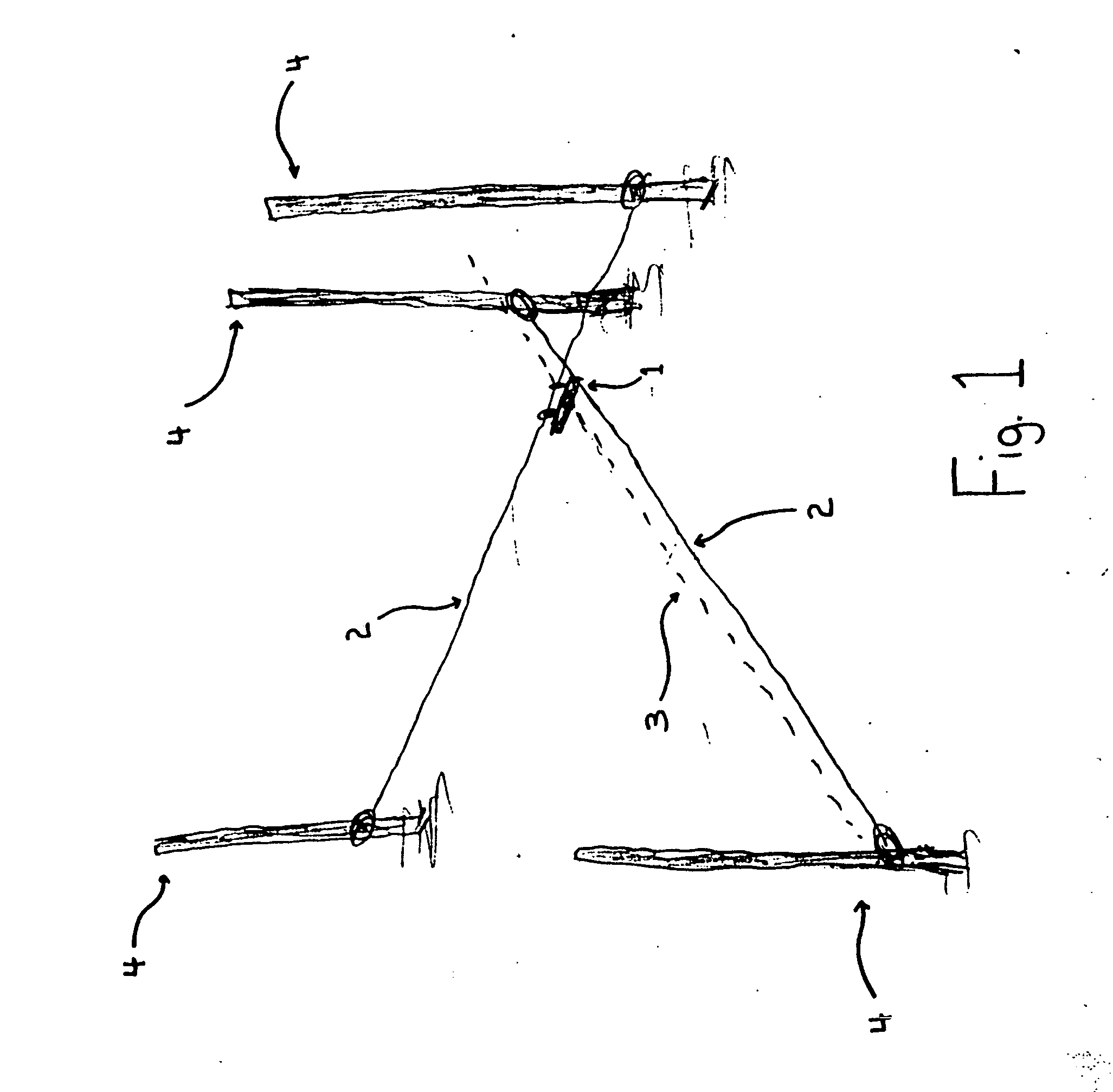
[0038]FIG. 1 shows a laser device 1 according to at least one embodiment of the present invention on a string or wire 2 tied between two stakes or posts 4 to define a corner. The laser device 1 is hung from the string 2 and projects a laser beam 3 out two sides to define a line substantially perpendicular to the string 2. Two additional stakes 4 are placed in the ground in the path of the laser beam 3. An additional string 2 is then tied between the two additional stakes 4, and thus a 90 degree angle is defined by the two strings 2. The intersection of the two strings 2 defines a corner for a square or rectangular building foundation. The process can be repeated for each of the other three corners.

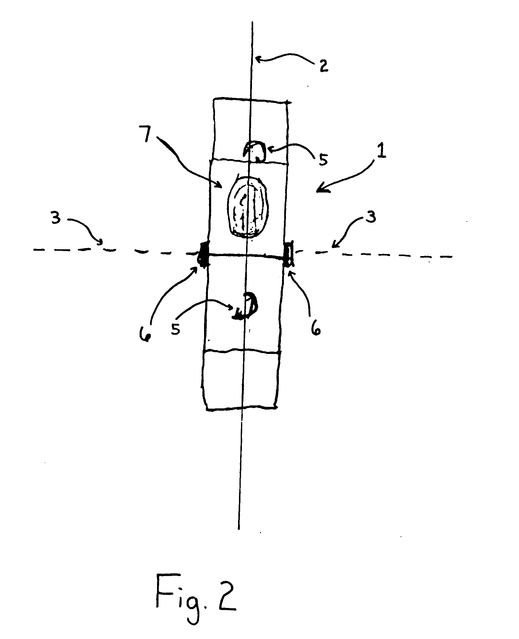
[0039]FIG. 2 shows a top close-up view of the laser device 1 shown in FIG. 1. The laser device 1 is hung from the string 2 by...


PUM


Abstract

An arrangement comprising a laser projection device is used in determining the location of corners in constructing a foundation of a building or other structure. The arrangement is also used in positioning wooden beams perpendicular to one another in a floor frame or similar structure.

Description

BACKGROUND OF THE INVENTION [0001] 1. Field of the Invention [0002] The present invention relates to an arrangement for use in determining the location of corners in constructing a foundation of a building or other structure. The present invention further relates to an arrangement for use in positioning wooden beams for a floor frame or similar structure. [0003] 2. Background Information [0004] In construction, it is well known that establishing a secure and well designed foundation is essential in constructing buildings, homes, and other large structures. Poorly designed foundations often create difficulty in construction and lessen the stability of the structure. It is very important to lay a foundation in the ground that corresponds as exactly as possible to the shape and dimensions of the structure to be built. Since most buildings and other structures are square or rectangular in shape, it is necessary to accurately measure and position the four corners of the foundation. If th...

Claims


Application Information

Patent Timeline
IPC IPC(8): G01C15/00
CPCG01C15/004Y10S33/21
Inventor ARMSTRONG, TIMOTHY D.HATHAWAY, GLENN T.
Owner ARMSTRONG TIMOTHY D
Why Eureka
Try Eureka