This helps you quickly interpret patents by identifying the three key elements:
Problems solved by technology
Method used
Benefits of technology
Benefits of technology
[0009] An object of the present invention is to provide a connecting device for frame members of a frame which facilitates assembly of the frame member to a corner member and setting and replacement of a showpiece to the frame by devising the corner member.
Problems solved by technology
Of them, a frame disclosed in Patent Document 1, in which a corner portion is formed by cutting end portions of frame members at an angle of 45° and butting their end portions, has a problem that when this frame is held by a hand, this resultant corner portion which is necessarily made sharp is likely to hurt the hand and another problem that it takes much time to carry out an assembly work of the frame members to the base.
The frame in Patent Document 2 is configured such that a corner member with a cap having a corner portion smoothed is provided on a base constituting a connecting device, and the cap is removed to allow placement and replacement of the showpiece from the front side of the frame when setting and replacing the showpiece, but has a problem that it is necessary to perform troublesome removal of caps from a plurality of corner members one by one and another problem that it takes much time to carry out an assembly work of the frame members to the corner members.
Further, the frames described in Patent Documents 1 and 2 have drawbacks and need improvement in the configuration of a connecting means for connecting the frame member to the base, an engaging means for stopping the frame member at the base in a closed state to fix the showpiece, a closing stop means for arresting the frame member to the base to prevent the frame member in the open state from free-falling, and so on.
Method used
Image
Click on the blue label to locate the original text in one second.
Reading with bidirectional positioning of images and text.
Examples
first embodiment
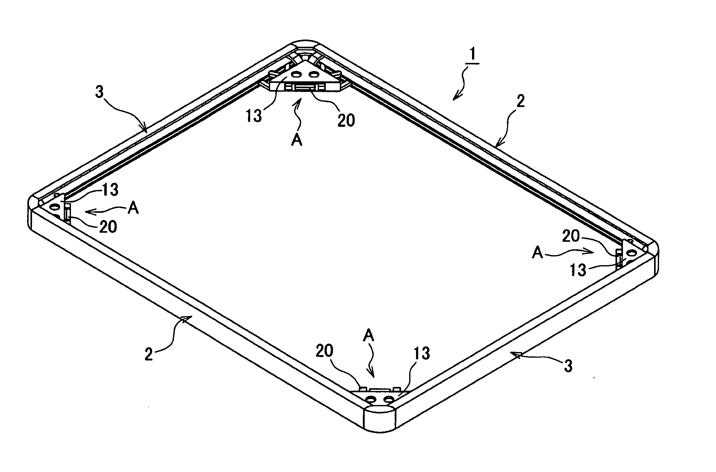
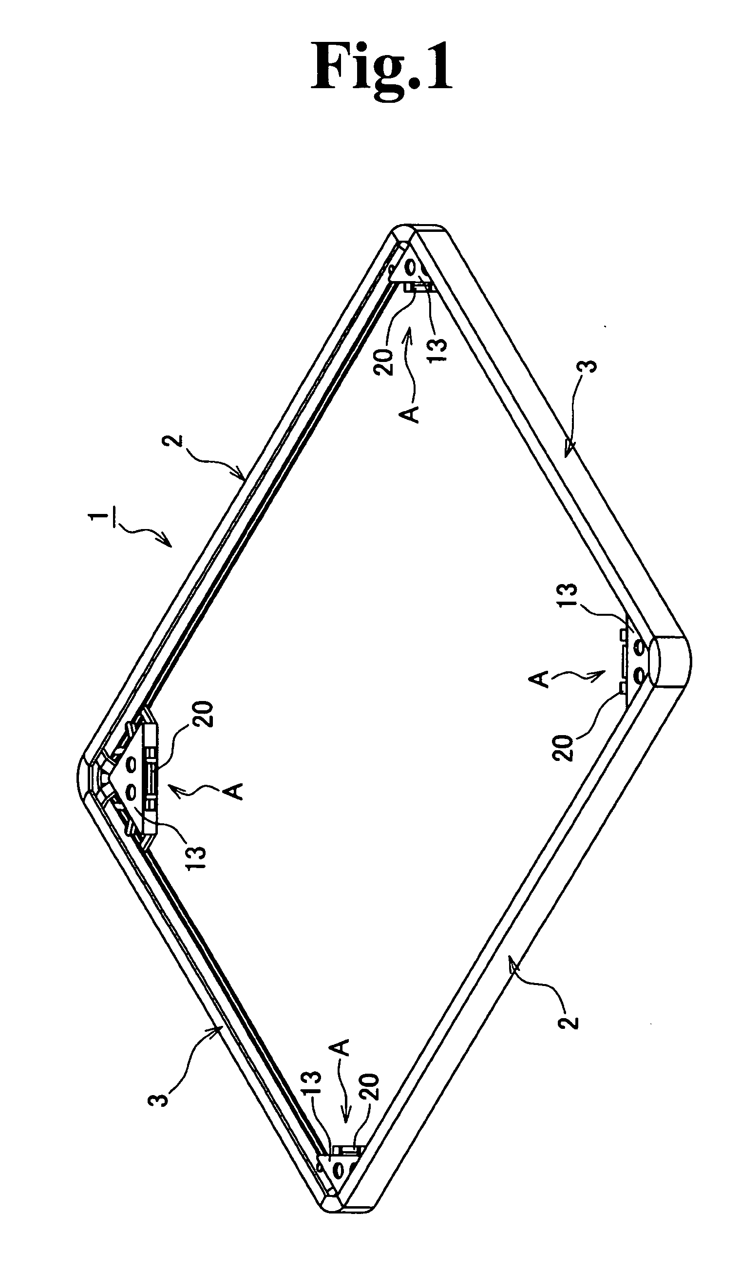
[0062]FIG. 1 shows a perspective view of the entire frame, in which a reference numeral 1 denotes a frame such as a picture frame, a poster frame, a jigsaw puzzle frame, and so on. The frame 1 is formed in a planar rectangular shape by connecting a pair of long frame members 2, 2 and a pair of short frame members 3, 3, the frame members of each pair having the same length, through use of four connecting devices A, A . . . . Incidentally, considerable planar shapes of the frame 1 include, not limited to the rectangular shape, other polygonal shapes such as a square shape, a triangular shape, and so on.
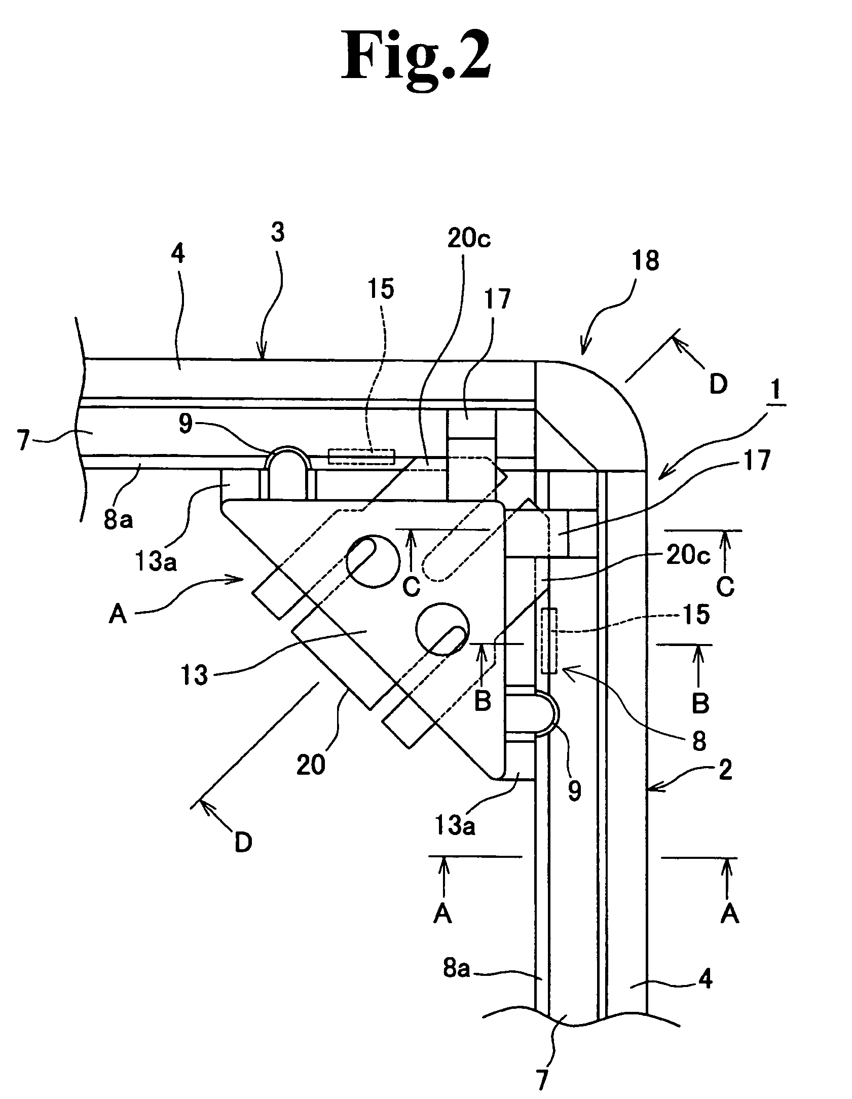
[0063] The frame member 2 or 3 is preferably made of aluminum and constituted of, as shown in FIG. 6 to FIG. 8 in particular, a base material portion 4; a pivotal attachment recess 5 located at the lower part of the base material portion 4; a showpiece arresting portion 6 provided at the upper part of the base material portion 4 in a manner to be curved inward; and a partition 7, locat...
second embodiment
[0080]FIG. 11 to FIG. 15 show another embodiment. With reference to the drawings, the stopper members 17, 17 shown in the first embodiment described above are omitted in a base 25 according to this embodiment. Even through the stopper members 17, 17 shown in the preceding embodiment are omitted, an upper side 27b of an open portion 27a of a pivotal attachment recess 27 pivotally attached to a hinge shaft portion 26 butts from the upper side against an extended portion 25a which is extended from the base 25 and provided with the hinge shaft portion 26 is provided as shown in FIG. 15 in particular, whereby long and short frame members 28, 29 closed can be stopped at right positions.
[0081] Further, in the second embodiment, a first engaging protruding piece 30 is provided to be located outside an engaging portion 31a on the free end side of a partition 31 as shown in FIG. 15 in particular, and a projection 30a provided to arrest the engaging portion 31a of the partition 31 to the firs...
third embodiment
[0085]FIG. 16 to FIG. 18 show still another embodiment of the connecting device according to the present invention. In this third embodiment, a hinge mechanism 41 for connecting a corner member 39, which is similarly desirably made of synthetic resin and whose corner portion is subjected to chamfering to be smoothed, to a base 40 and a first stopper means 42 are not sufficiently illustrated but are the same as those in the second embodiment. An opening stop means 43 of the corner member 39 is constituted of an engaging tongue piece 44 provided to protrude from the corner member 39 and provided with an engaging portion 44a at its free end side and an engagement guide portion 45 provided to protrude toward the base 40 side and provided with a protrusion 45a on its upper portion for arresting the engaging portion 44a of the engaging tongue piece 44 thereto.
[0086] The above configuration allows the corner member 39 to stop at a predetermined open position when it is opened, by engageme...
PUM
Abstract
A connecting device for frame members of a frame which facilitates setting and replacement of a showpiece to the frame particularly by devising how to attach a corner member and a frame member is provided. A connecting device for connecting each corner portion of a plurality of frame members constituting a frame such as a picture frame, a poster frame, a jigsaw puzzle frame, and so on is constituted of: a base to which an end portion of each of the frame members is attached to be rotatable in a direction perpendicular to an axial direction thereof; a locking means attached to the base for locking each frame member in an inwardly closed state; and a corner member with a smoothed corner which forms each corner portion of the frame, wherein the corner member is swingably attached to the base. The present invention can also employ all or part of a closing stop means for stopping the frame member at a predetermined position when it is closed to the base; an opening stop means for stopping the frame member at a predetermined position when it is opened from the base; and a stop means for stopping the frame member at a predetermined position when it is closed.
Description
FIELD AND BACKGROUND OF THE INVENTION [0001] The present invention relates to a connecting device for frame members constituting a frame such as a picture frame for pictures and photographs, a poster frame on which a poster is put, a jigsaw puzzle frame for exhibiting a completed jigsaw puzzle, and so on. DESCRIPTION OF THE RELATED ART [0002] In place of frames such as a picture frame, a poster frame, and so on into which a showpiece is placed by fitting the showpiece together with a transparent plate and a retaining plate into a fixing frame in a planar quadrilateral or triangular shape from its back face and securing the retaining plate through use of engaging pieces attached to the rear side of the frame members of the fixing frame to prevent falling off of the showpiece, such many frames are recently available that are configured such that end portions of frame members constituting the frame are connected to a base to be openable thereto / closable therefrom to allow a showpiece t...
Claims
Application Information
Patent Timeline
Application Date:The date an application was filed.
Publication Date:The date a patent or application was officially published.
First Publication Date:The earliest publication date of a patent with the same application number.
Issue Date:Publication date of the patent grant document.
PCT Entry Date:The Entry date of PCT National Phase.
Estimated Expiry Date:The statutory expiry date of a patent right according to the Patent Law, and it is the longest term of protection that the patent right can achieve without the termination of the patent right due to other reasons(Term extension factor has been taken into account ).
Invalid Date:Actual expiry date is based on effective date or publication date of legal transaction data of invalid patent.

