

Conveyor apparatus for an assembly line
- Summary
- Abstract
- Description
- Claims
- Application Information
AI Technical Summary
Benefits of technology
Problems solved by technology
Method used
Image

Examples
Embodiment Construction
[0033]In the diagrams, like numbers refer to like objects throughout. Objects in the diagrams are not necessarily drawn to scale.
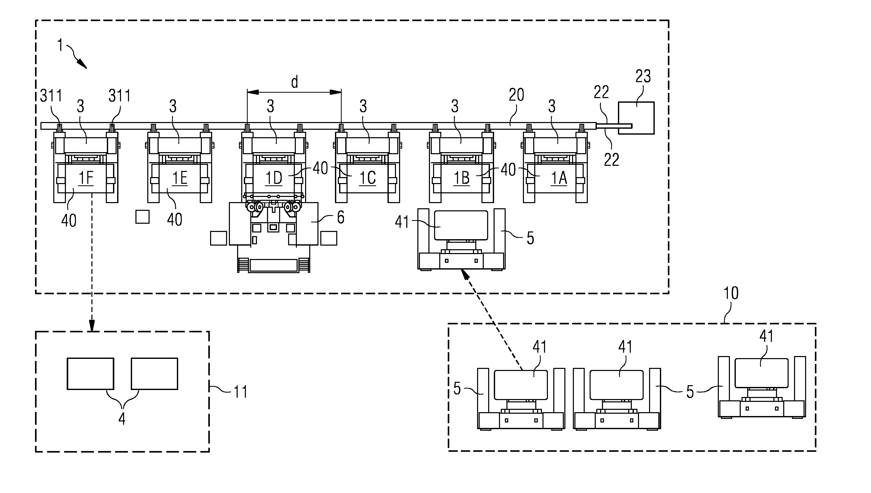
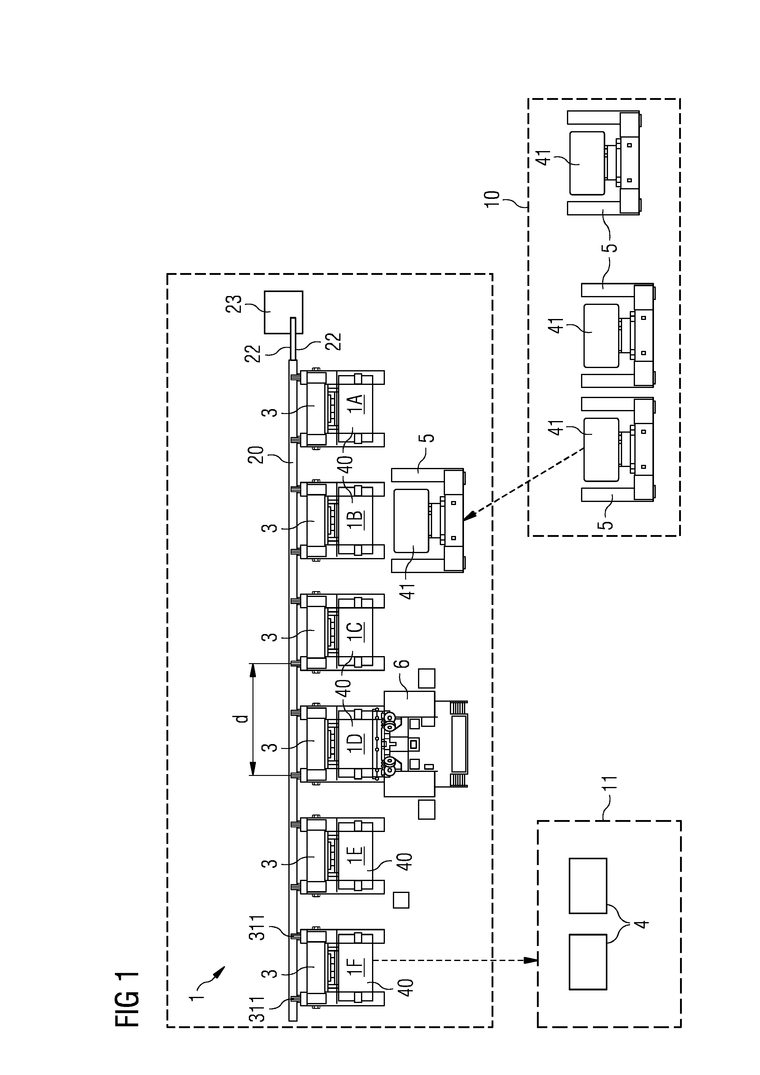
[0034]FIG. 1 shows a schematic plan view of an assembly line 1 according to the application at a first time instant. The assembly line 1 is used to assemble a component 4 for a wind turbine, more specifically to assemble a generator 4 for a direct drive wind turbine. The assembly line 1 comprises six distinct assembly stages 1A, . . . , 1F. At each assembly stage 1A, . . . , 1F a rotor transport frame 3 is positioned. A conveyor apparatus 2 according to the application is used to convey a rotor transport frame 3 from one assembly stage 1A, . . . , 1E to the next 1B, . . . , 1F. Each stage 1A, . . . , 1F can be dedicated to a specific assembly step, as outlined in the introduction. For example, at the second assembly stage 1B shown here, a stator 41 can be merged with a partially assembled rotor 40. The stator 41 can be transported to the assembly line 1 us...
PUM
| Property | Measurement | Unit |
|---|---|---|
| Distance | aaaaa | aaaaa |
Abstract
Description
Claims
Application Information