
Ultrasonic inspection apparatus for inspecting a workpiece

Active Publication Date: 2009-08-18
AGFA NDT
View PDF9 Cites 4 Cited by
  • Summary
  • Abstract
  • Description
  • Claims
  • Application Information

AI Technical Summary

Benefits of technology

[0009]This is where the invention comes in. It seeks to facilitate the work performed by the operator and to provide him with an ultrasonic inspection apparatus that clearly indicates the quality of a coupling and of an echo sequence without the operator having to mind details in the A-scan.
[0012]The respective at least one signal value shown on the bar display is directly indicative of the quality. In practice, when performing the inspection, the operator can substantially concentrate on the A-scan and keep an eye on the bar display besides; he needs not direct his full attention toward the bar display. The information the bar display shows is in principle contained in the A-scan as well. Thus shown on the bar display, the corresponding indications are allowed to be better registered by the operator and are displayed more prominently. Details of the A-scan are easy to distinguish in the bar display where they are displayed in a more dramatic way, more specifically in a particular colour so as to be readily noticeable. This facilitates the ultrasonic inspection and more specifically aids in keeping the attention of the operator for a long time.
[0019]In a preferred developed implementation, the bar display is disposed in the nearest possible proximity to the monitor or is part thereof. The operator may thus easily associate it with the A-scan without having to direct its full attention toward the bar display.

Problems solved by technology

Experience has shown that with the prior art ultrasonic inspection apparatus it is extremely difficult to care for both good coupling and good echo sequences.
This places high demands on the operator of the ultrasonic inspection apparatus.

Method used


Image

  • Ultrasonic inspection apparatus for inspecting a workpiece
  • Ultrasonic inspection apparatus for inspecting a workpiece
  • Ultrasonic inspection apparatus for inspecting a workpiece

Examples


Embodiment Construction

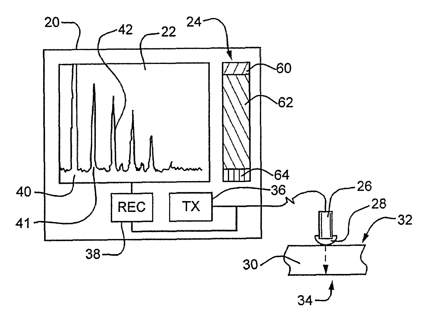
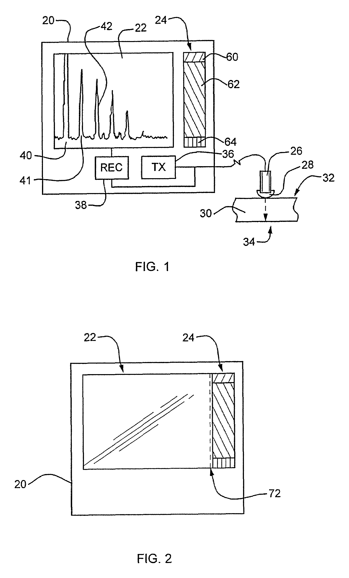
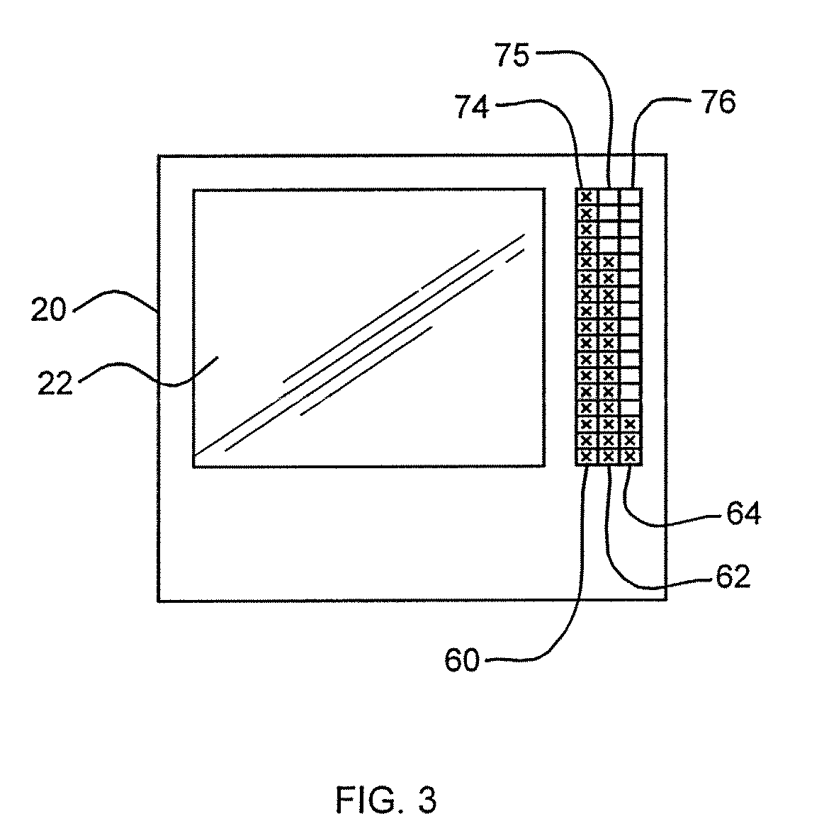
[0027]In a housing 20 of an ultrasonic inspection apparatus there is disposed a monitor 22, which may for example be an LCD-display. A bar display 24 is disposed immediately beside it and parallel thereto. Said bar display also is an LCD-display. The bar display 24 has the same height dimension as the monitor 22. The bar display 24 is narrow; its width is of between 10 and 20 mm. Like the monitor 22, the bar display 24 is substantially defined by a rectangle.

[0028]A transmit / receive probe 26 is connected to the housing through a plug type connection. Its structure is basically known, the reader is referred to the above mentioned German book for example. At its front end, it has a couplant 28. Here, the couplant 28 is implemented as a chamber filled with water and bounded by a thin plastic film, for example a latex film. The couplant 28 simultaneously is a preliminary distance. The couplant 28 permits to directly contact a workpiece 30 without inclusion of air bubbles and the like.

[0...


PUM


Abstract

The invention relates to an ultrasound control device for non-destructively inspecting a workpiece. The inventive ultrasound control device comprises a transmitting-receiving sensor provided with an element for connecting to the input surface of a controlled workpiece, a transmitter which is connected to the sensor and sends pulses produced thereby to said sensor, a receiver connected to the sensor and a screen which is connected to the receiver for displaying electric echo signals received by the receiver. The sensor transmits ultrasound pulses which, on one hand are reflected by the input surface and return to said sensor, and penetrate into the workpiece and are reflected at least once by the back wall thereof, on the other hand. Said ultrasound control device also comprises a bar display for visualising the received electric echo signals. At least one signal value displayed on said display in a real time results from one of electric echo signals reflected by the input surface: an input echo reflected by the input surface, at least one echo from the back wall and / or one signal calculated on the basis of several echoes reflected thereby.

Description

FIELD OF THE INVENTION[0001]The invention relates to an ultrasonic inspection apparatus for non-destructive inspection of a workpiece, said ultrasonic inspection apparatus having a transmit / receive probe comprising a couplant for coupling to an entrance surface of the workpiece, a transmitter connected to said probe and generating transmit pulses which it then delivers to said probe, a receiver connected to said probe and a monitor that is connected to said receiver for displaying electric echo signals received by said receiver. The probe emits ultrasonic pulses that, on the one side, are reflected at the entrance surface back to the probe and on the other side penetrate the workpiece where they are reflected at least once at a backwall of the workpiece.Description of the Related Art[0002]For ultrasonic non-destructive inspection of a workpiece, suited inspection apparatus are known. General reference is made to the German book J. and H. Krautkrämer, Werkstoffprüfung mit Ultraschall...

Claims


Application Information

Patent Timeline
IPC IPC(8): G06F19/00G01B17/02G01N29/06G01N29/11
CPCG01B17/02G01N29/0609G01N29/0645G01N29/11G01N2291/2672G01N2291/044G01N2291/101G01N2291/2632G01N2291/02854
Inventor BUSCHKE, PAULKIRCHNER, BERND
Owner AGFA NDT
Features
  • Generate Ideas
  • Intellectual Property
  • Life Sciences
  • Materials
  • Tech Scout
  • Unparalleled Data Quality
  • Higher Quality Content
  • 60% Fewer Hallucinations
Learn More