Pierce joint terminal, and assembly of pierce joint terminal and circuit member

Active Publication Date: 2006-04-13
YAZAKI CORP
View PDF5 Cites 0 Cited by
  • Summary
  • Abstract
  • Description
  • Claims
  • Application Information

AI Technical Summary

Benefits of technology

[0006] Specifically, the maximum space between the connection pawls is required to be smaller than the width of a conductive portion, and a conductive portion with a small width easily causes the above problem.
[0007] The invention is directed

Problems solved by technology

Specifically, the maximum space between the connection pawls is required to be smaller than the width

Method used


Image

  • Pierce joint terminal, and assembly of pierce joint terminal and circuit member
  • Pierce joint terminal, and assembly of pierce joint terminal and circuit member
  • Pierce joint terminal, and assembly of pierce joint terminal and circuit member

Examples


second embodiment

[0040] With reference to FIG. 8, a pierce joint terminal 1B includes a circular base portion 6, and three connection pawls 7 raises from the outer peripheral edge of the base portion 6. Three connection pawls 7 are provided to integrally extend outwardly at equally spaced positions of the outer circular peripheral edge of the base portion 6, that is, over an entire circumference thereof, and they are respectively bent to rise.

[0041] Pierce joint terminals 1B are coupled using a carrier 9 like the first embodiment. The carrier 9 includes a carrier frame 9a as a straight line. The carrier 9 includes extension portions 9b extended from the one-side edge of the carrier frame 9a at equal intervals and in a direction orthogonal to the carrier frame 9a. Each distal end of the extension portion 9b is connected to the base portion 6 of the pierce joint terminal 1B. The connecting portion of the circular base portion 6 and the extension portion 9b is one end of the circle. The orientation of...


PUM


Abstract

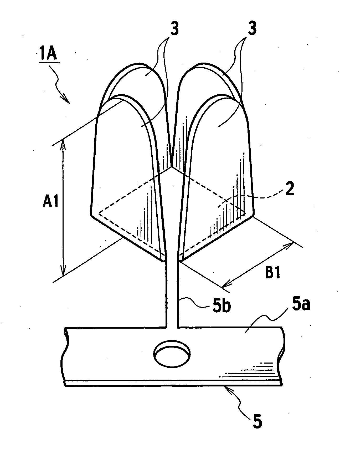
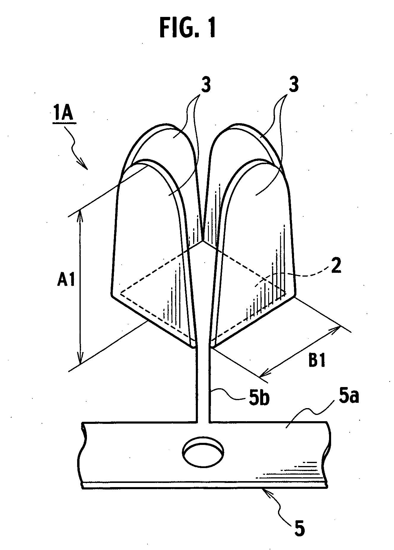
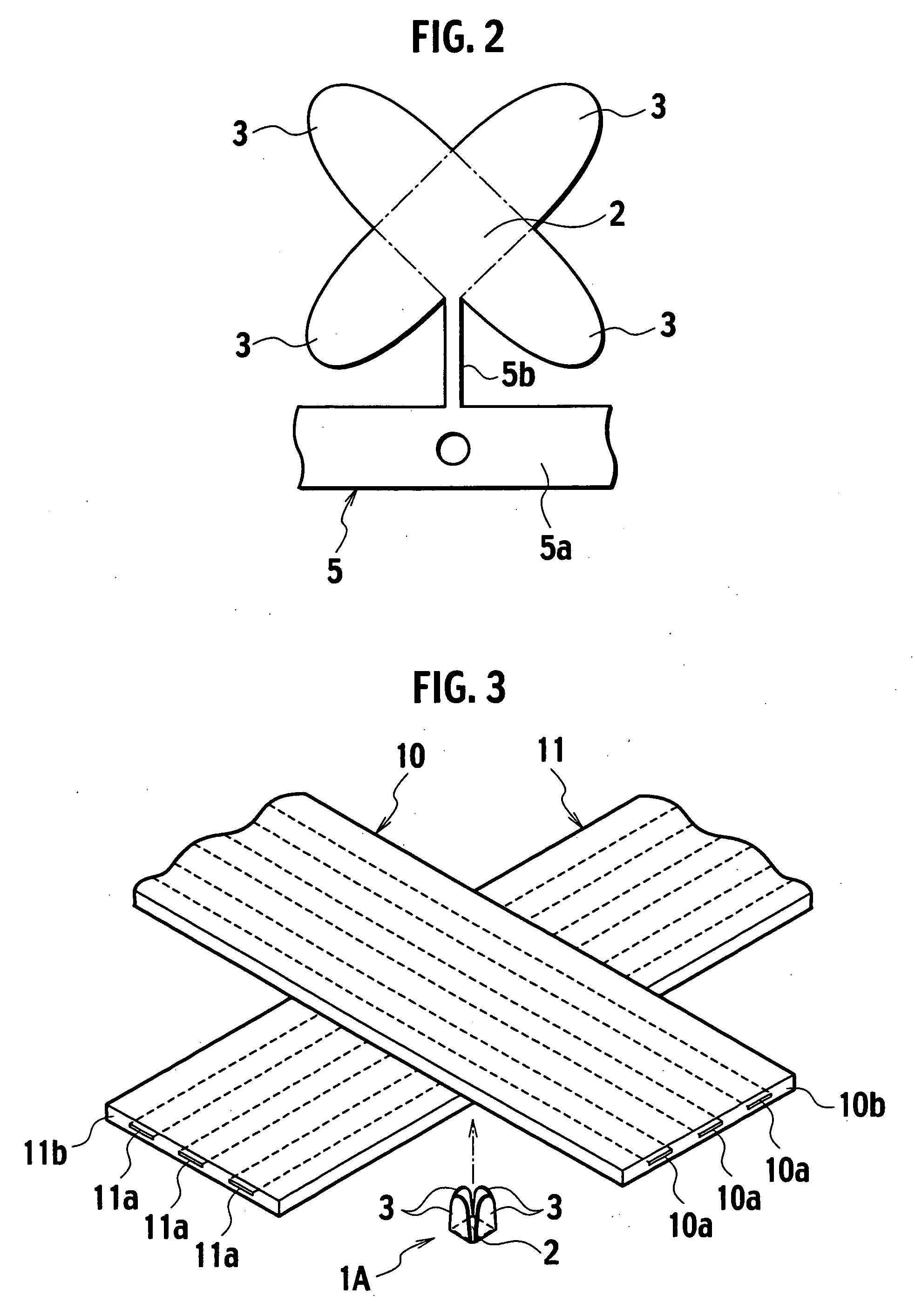
A pierce joint terminal includes a base. The terminal includes a contact raised from an outer periphery of the base and configured to pierce a circuit member to be crimped for establishing electric contact with a conductor within the circuit member.

Description

CROSS-REFERENCE TO RELATED APPLICATIONS [0001] This application is based upon and claims the benefit of priority from Japanese Patent Application No. 2004-298813 filed on Oct. 13, 2004; the entire contents of which are incorporated herein by reference. BACKGROUND OF THE INVENTION [0002] The invention relates to a pierce joint terminal, and an assembly of a pierce joint terminal and a circuit member. According to the invention, the contact of the pierce joint terminal pierces into the circuit member such as a flat cable to crimp the end of the contact projecting through the circuit member, thus establishing electric contact with a conductive portion within the circuit member. [0003] A related art of the pierce joint terminal is disclosed in, for example, Japanese Patent Application Laid-open No. S63-13285. [0004] A pierce joint terminal has a flat plate-shaped base portion. The base portion has square holes at two portions thereof. Each peripheral edge of the holes constitutes the in...

Claims


Application Information

Patent Timeline
IPC IPC(8): H01R11/20
CPCH01R4/245H01R12/616
Inventor MAITANI, YUKIHIROKUMAKURA, HIDETO
Owner YAZAKI CORP
Why Eureka
Try Eureka