Floor drain with built-in sediment trap and removable gas trap
- Summary
- Abstract
- Description
- Claims
- Application Information
AI Technical Summary
Benefits of technology
Problems solved by technology
Method used
Image

Examples
Embodiment Construction
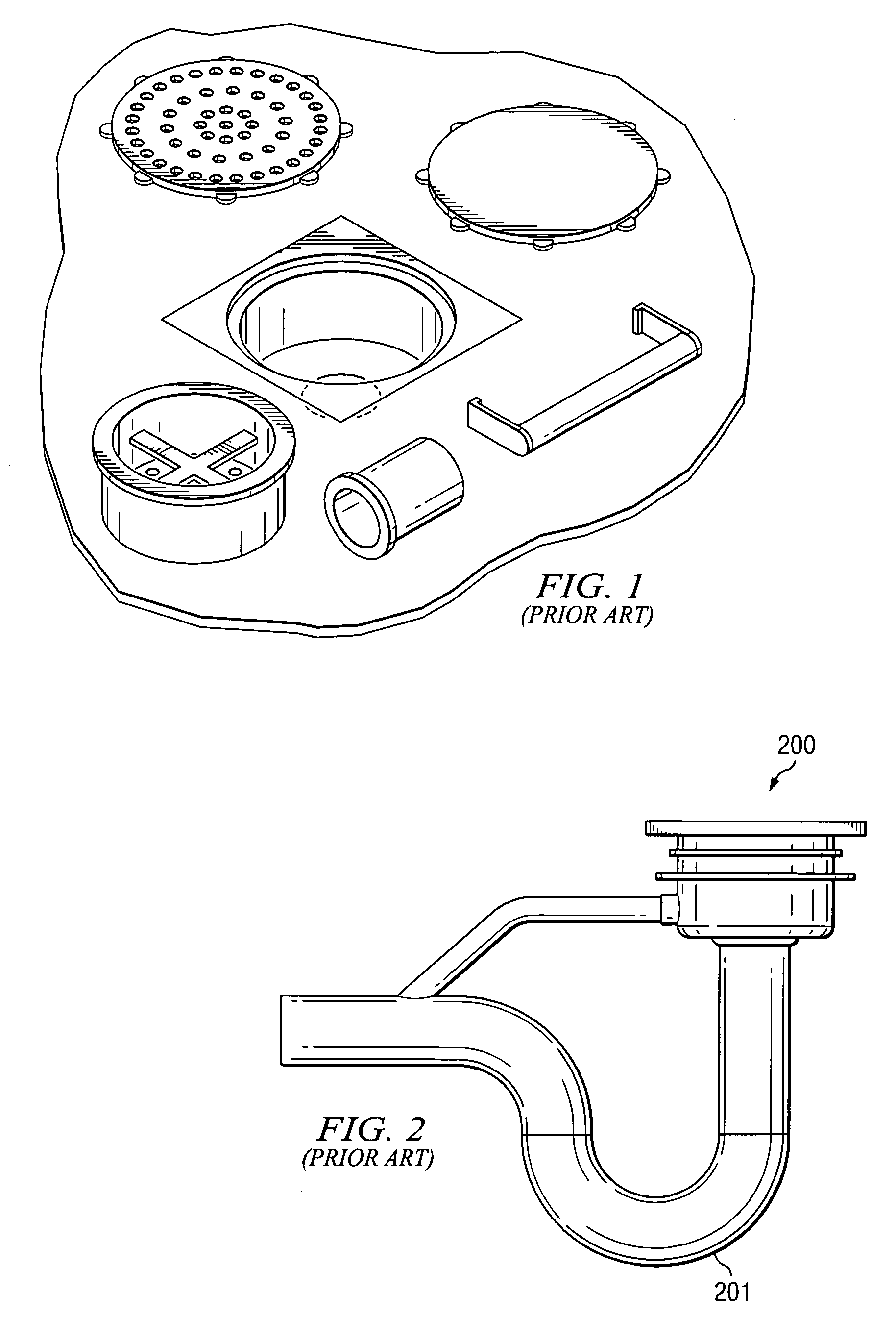
[0019]FIG. 1 is an illustration of the disassembled parts of a conventional floor drain assembly made of a plastic or polypropylene material.
[0020]FIG. 2 is a side view illustration of a conventional floor drain assembly showing trap 201. As seen in FIG. 2, the trap 201 of drainage is the curved section of drain line that prevents sewer odors from escaping into the atmosphere. Disadvantageously, the trap 201 is fixed in position and cannot be easily removed to unclog the drain or to engage in maintenance.
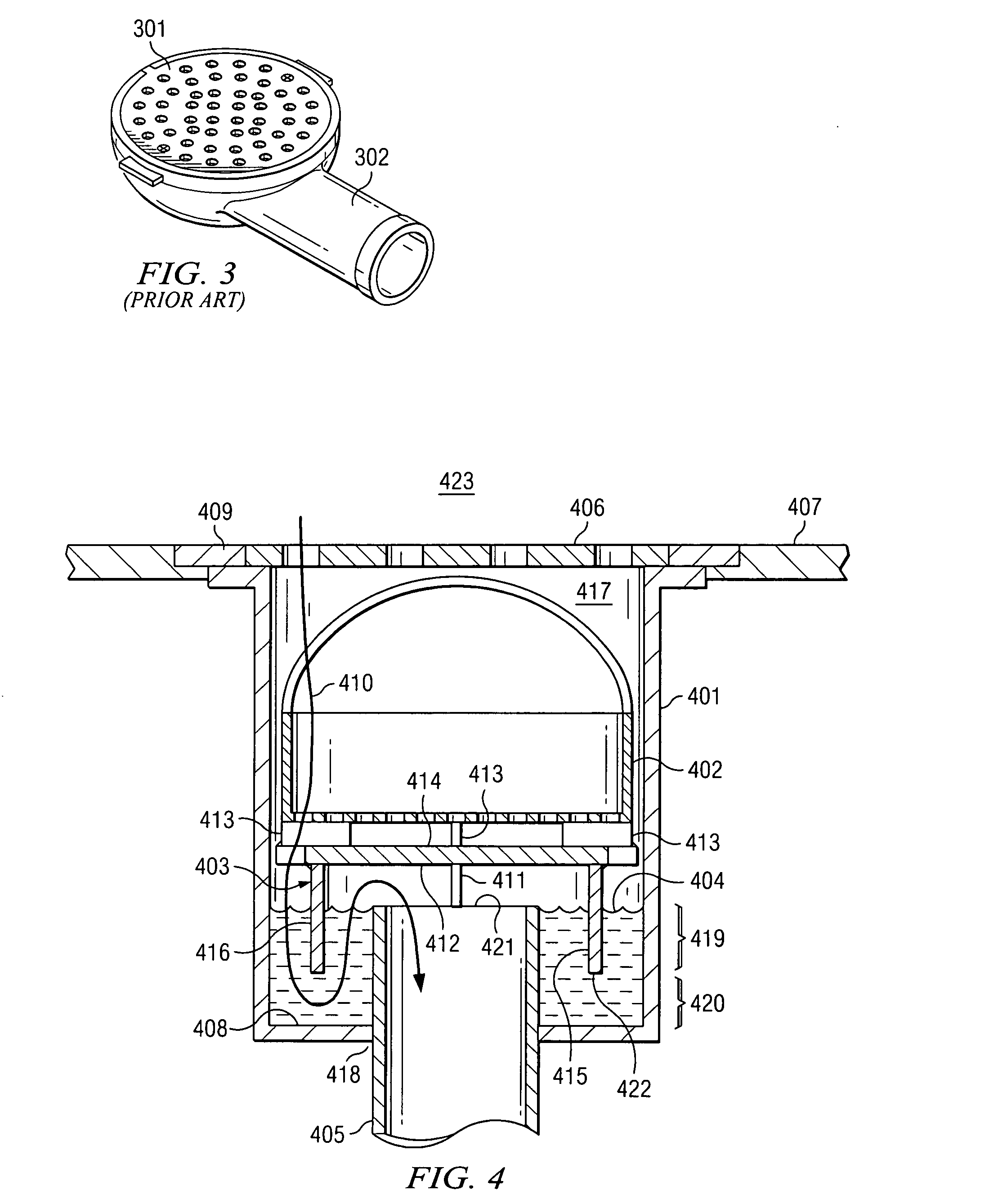
[0021]FIG. 3 is a front perspective view of a conventional floor drain assembly that has not been installed in a floor. The conventional drain assembly has a lid 301 with holes for liquids to flow and a trap 302 that serves as a aqueous barrier to gas.
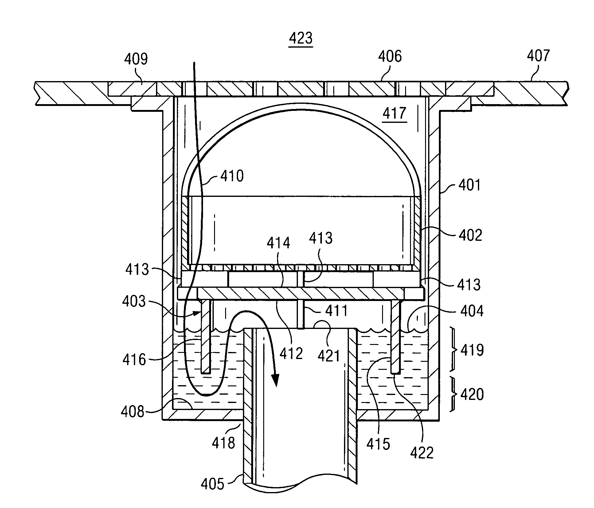
[0022]FIG. 4 is a cutaway side view of the present invention showing the various components thereof and the drainage flow path. As seen therein, the present invention comprises a main housing 401, whose inner wall defines drainage b...
PUM
 Abstract
Description
Claims
Application Information
 - R&D Engineer
- R&D Manager
- IP Professional
- Industry Leading Data Capabilities
- Powerful AI technology
- Patent DNA Extraction
Browse by: Latest US Patents, China's latest patents, Technical Efficacy Thesaurus, Application Domain, Technology Topic.
© 2024 PatSnap. All rights reserved.Legal|Privacy policy|Modern Slavery Act Transparency Statement|Sitemap