
Hub unit with sensor

a technology of sensor and hub, which is applied in the direction of instruments, apparatus for force/torque/work measurement, ways, etc., can solve the problem that the ground contact load cannot be obtained with high accuracy from the measurement of the strain sensor, and achieve the effect of high accuracy and direct and accurate measuremen

Inactive Publication Date: 2005-01-27
JTEKT CORP
View PDF9 Cites 36 Cited by
  • Summary
  • Abstract
  • Description
  • Claims
  • Application Information

AI Technical Summary

Benefits of technology

[0010] The ground contact load on the tire thus obtained is used as slip ratio substituting data for ABS control and is used also for controlling the drive force or brake force, thus contributing to improvements in the accuracy of vehicle control.
[0013] The strain of the body-side raceway member can be measured directly and accurately by the strain sensor as provided on the curved base end part of the flange of the body-side raceway member, so that the force exerted by the ground on the body-side raceway member, i.e., the ground contact load, is detectable accurately. Moreover, there is no need to use a member for supporting the strain sensor on the body-side raceway member, and the ground contact load measuring sensor device can be installed on the vehicle without increasing the number of parts or without necessitating an additional space for the installation.
[0015] The ground contact load acting on each tire varies with variations in the velocity of the running vehicle or with the alterations of the posture of the vehicle. At this time, the flange portion of the body-side raceway member connected to the vehicle body with bolts deforms relative to the cylindrical portion. Accordingly, variations in the ground contact load appear as variations in the amount of deformation of the flange portion relative to the cylindrical portion, and these variations are measured as variations in the distance between the cylindrical portion (or the flange portion) and the displacement sensor by the sensor fixed to the flange portion (or the cylindrical portion). Variations in the ground contact load can conversely be calculated from variations in this distance. In this way, the displacement of the flange portion of the body-side raceway member is detected by the displacement sensor relative to the cylindrical portion thereof, so that the amount of deformation of the body-side raceway member can be measured directly and accurately. The force exerted by the ground on the body-side raceway member, i.e., the ground contact load, is therefore detectable with high accuracy.

Problems solved by technology

However, since the conventional hub unit having a sensor is adapted to measure the stain of the annular support member, the ground contact load determined from the strain involves a great error, so that the hub unit has the problem that the ground contact load can not be obtained with high accuracy from the measurement of the strain sensor.

Method used


Image

  • Hub unit with sensor
  • Hub unit with sensor
  • Hub unit with sensor

Examples


Embodiment Construction

[0024] Embodiments of the invention will be described below with reference to the drawings.

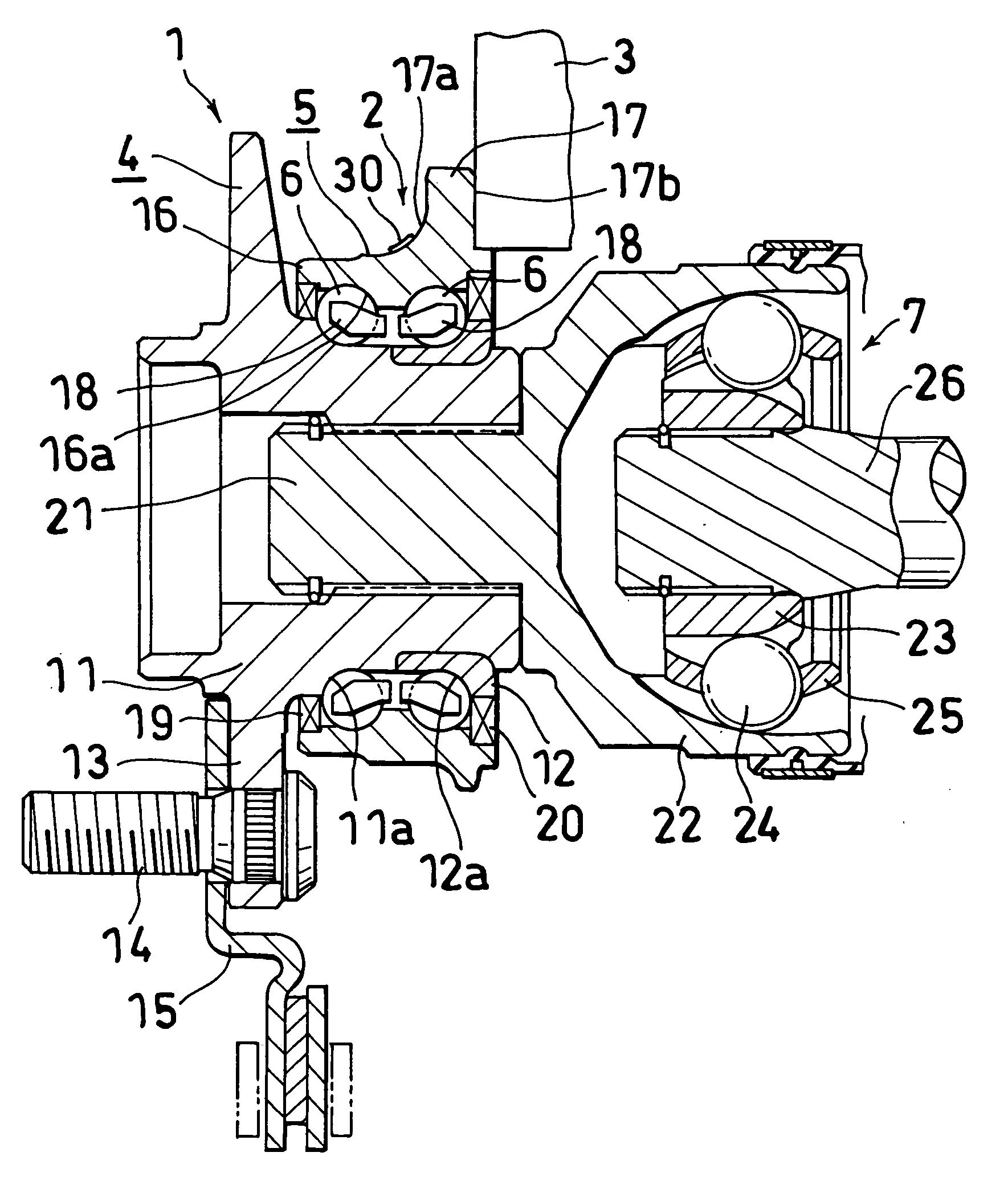
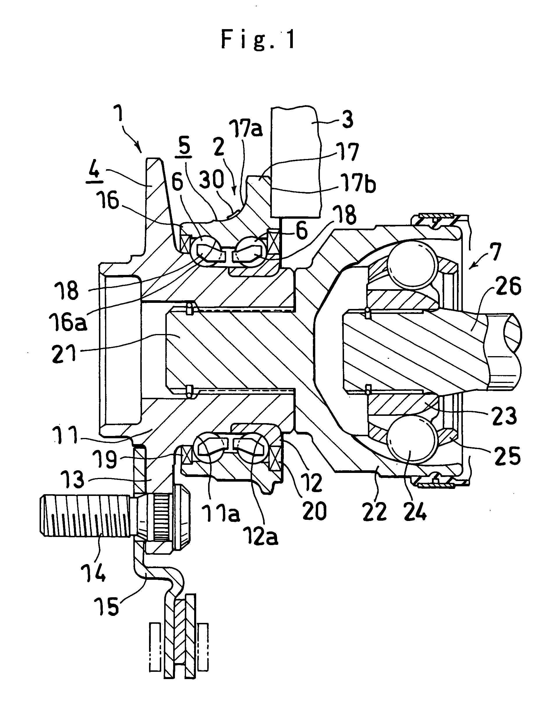
[0025]FIGS. 1 and 2 show a first embodiment of hub unit having a sensor according to the invention. In the following description, the left- and right-hand sides of FIG. 1 will be referred to as the “left” and “right,” respectively. The left side is the outside of the vehicle, and the right side is the inside of the vehicle.

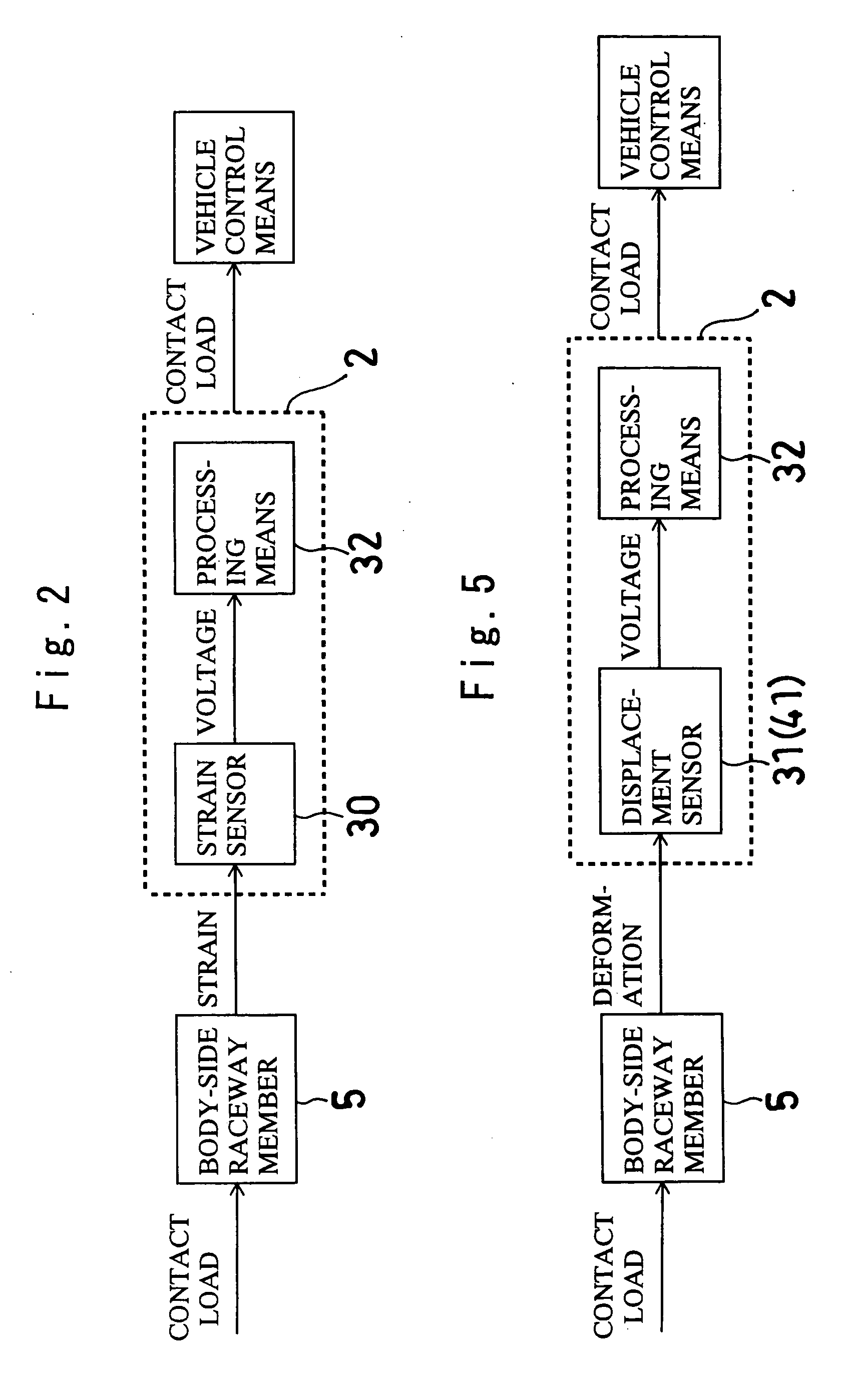
[0026] With reference to FIG. 1, the hub unit having a sensor of the first embodiment comprises a hub unit 1 having a wheel-side raceway member 4 to which a wheel (not shown) is to be attached, a body-side raceway member 5 to be fixed to a vehicle body 3 and two rows of rolling bodies 6 arranged between the two raceway members 4, 5, and a sensor device 2 provided on at least one of the two raceway members 4, 5 of the hub unit 1.

[0027] The hub unit 1 is of the type for use on drive wheels of motor vehicles and is coupled to a constant velocity joint 7.

[0028] The wheel-sid...


PUM


Abstract

A hub unit having a sensor comprises a hub unit 1 having a wheel-side raceway member 4, a body-side raceway member 5 and two rows of rolling bodies 6, and a sensor device 2 provided on the hub unit 1. The body-side raceway member 5 has a cylindrical portion 16 and a flange portion 17 provided with an insertion hole for a bolt for fastening the hub unit 1 to a vehicle body. The sensor device 2 has a magnetic sensor 31 supported by a support member 33 fixed to the flange portion 17 and serving as a displacement sensor for detecting variations in the distance between the sensor and the cylindrical portion 16. A magnetized portion 34 is provided on the cylindrical portion 16 at a location opposed to the sensor.

Description

TECHNICAL FIELD [0001] The present invention relates to hub units which have a sensor and which are each in the form of an assembly comprising a hub unit serving as a component of a motor vehicle and a sensor device joined to the hub unit for detecting various items of data as to the motor vehicle. BACKGROUND ART [0002] Since various items of data are required for controlling motor vehicles, it has been proposed to provide a sensor on a hub unit comprising a wheel-side raceway member to which a wheel is to be attached, a body-side raceway member to be fixed to the vehicle body, and two rows of rolling bodies arranged between the two raceway members. [0003] For example, the publication of JP-A No. 1991-209016 discloses a sensor-equipped hub unit wherein an annular support member is attached to the inner end face of a body-side raceway member and provided with a stain sensor. [0004] The control means recently in use for motor vehicles include drive force control means not permitting p...

Claims


Application Information

Patent Timeline
IPC IPC(8): G01L5/00G01P3/44
CPCB60B27/0026B60B27/0042B60B27/0068B60B27/0084G01L5/0023B60G2204/115B60T2240/06G01L5/0019B60G17/019F16C41/00F16C19/186F16C19/522F16C2326/02
Inventor INOUE, MASAHIRO
Owner JTEKT CORP
Features
  • Generate Ideas
  • Intellectual Property
  • Life Sciences
  • Materials
  • Tech Scout
  • Unparalleled Data Quality
  • Higher Quality Content
  • 60% Fewer Hallucinations
Learn More