
Hill holding brake system for hybrid electric vehicles

a hybrid electric vehicle and holding brake technology, applied in the direction of braking systems, electric devices, propulsion by batteries/cells, etc., can solve the problems of limited power capacity, limited range of electric vehicles, and substantial amount of time for battery recharge, so as to improve the operating efficiency and driveability of hybrid electric vehicles.

Inactive Publication Date: 2005-01-27
FORD GLOBAL TECH LLC
View PDF10 Cites 60 Cited by
  • Summary
  • Abstract
  • Description
  • Claims
  • Application Information

AI Technical Summary

Benefits of technology

The present invention is a method and system for controlling a hybrid vehicle during a hill holding condition. The invention improves the operating efficiency and driveability of the vehicle by using an electro-hydraulic brake system instead of traditional engine or starter generator motor braking torque. The electronic brake control system actuates the electro-hydraulic brakes to hold the vehicle on the hill, while the powertrain control module turns off the internal combustion engine. The invention allows for more efficient and effective holding of the vehicle on a hill, improving its overall performance and driving experience.

Problems solved by technology

However, electric vehicles have limited range, limited power capabilities, and require a substantial amount of time to recharge the battery.
The internal combustion engine in a hybrid electric vehicles wastes fuel and produces undesirable emissions to hold the vehicle on a hill because the internal combustion engine must continue to operate while the vehicle is stopped.
However, the use of the integrated starter generator motor in a hybrid electric vehicle wastes battery power and requires additional cooling during hill holding conditions.

Method used


Image

  • Hill holding brake system for hybrid electric vehicles
  • Hill holding brake system for hybrid electric vehicles
  • Hill holding brake system for hybrid electric vehicles

Examples


Embodiment Construction

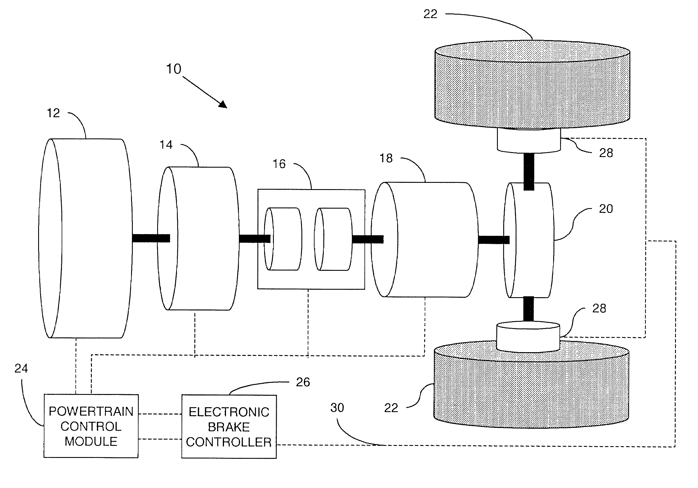
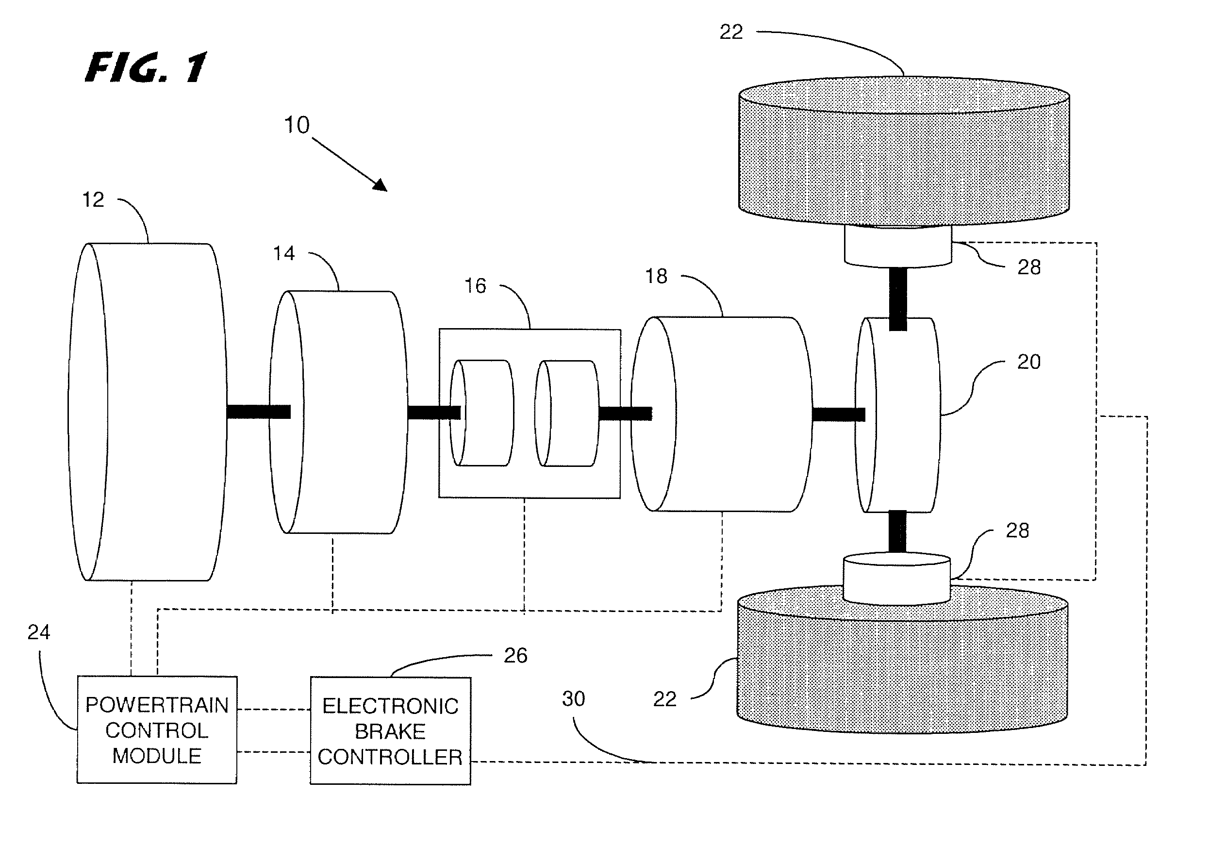
[0035] Referring now to the drawings figures, there is illustrated in FIG. 1 a representative configuration of a hybrid electric vehicle 10 having a internal combustion engine 12 coupled to an integrated starter generator motor 14. The two powerplants are coupled by a clutch 16 to a transmission 18, and a differential 20 to provide torque to a set of vehicle wheels 22. A powertrain control module 24 controls the operating parameters of the internal combustion engine 12 and the integrated starter generator motor 14. An electronic brake control system 26 controls a set of electro-hydraulic brakes 28. Both controllers are shown as logical units, and can be embodied in one or more separate controller or computer-controlled devices. A vehicle communication data network 30 enables communications between the hybrid electric vehicle components, the electronic brake controller 26 and the powertrain control module 24 at suitable update rates.

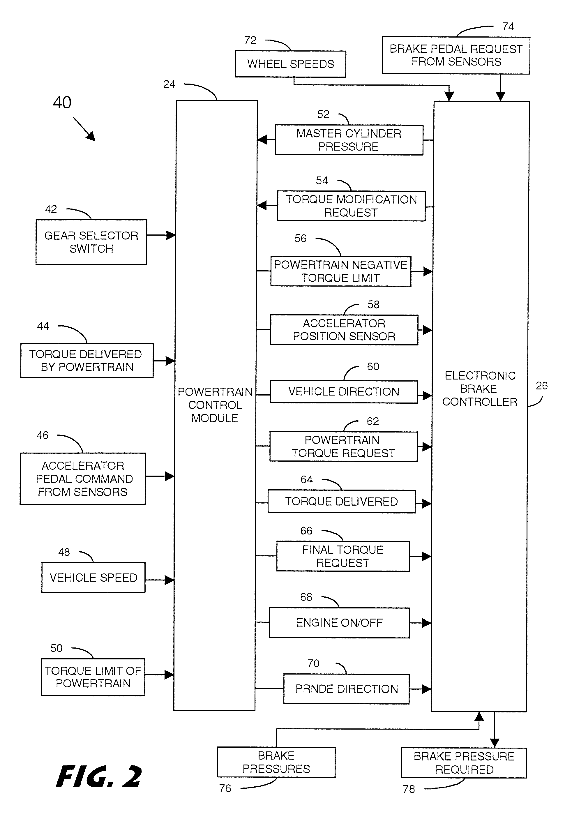
[0036] The powertrain control module 24 provides a...


PUM


Abstract

A hill holding function of a hybrid electric vehicle is initiated when the powertrain control module determines that a hill holding condition exists. In the hill holding condition, the electro-hydraulic brakes will provide brake torque to each wheel and the powertrain control module will turn off the internal combustion engine. The system can also detect a two footer condition where the vehicle operator requests both acceleration torque and brake torque simultaneously. The hill holding function of the hybrid electric vehicle in a two footer situation will apply the electro-hydraulic brakes and turn off the internal combustion engine. When the operator requests acceleration in either the hill holding or the two footer condition, the electric brake controller will transition the release of the electro-hydraulic brakes and the powertrain control module will turn on the internal combustion engine.

Description

BACKGROUND OF INVENTION [0001] 1. Field of the Invention [0002] The present invention relates generally to a braking system for a hybrid electric vehicle and, more particularly, to a hill holding brake system for a hybrid electric vehicle. [0003] 2. Background Art [0004] A conventional wheeled automotive vehicle includes an internal combustion engine powered by fossil fuels. The desire to reduce emissions and consumption of fossil fuels in an internal combustion engine vehicle is well established. [0005] An electric vehicle comprises a battery and an electrical generator motor powerplant system to provide torque to a set of wheels. However, electric vehicles have limited range, limited power capabilities, and require a substantial amount of time to recharge the battery. Additionally, electric vehicles require the development of an extensive infrastructure to recharge the battery and service the electric vehicles. [0006] A hybrid electric vehicle includes a conventional internal comb...

Claims


Application Information

Patent Timeline
Patent Type & Authority Applications(United States)
IPC IPC(8): B60K6/46B60W10/06B60W10/08B60W10/18B60W20/00
CPCB60K6/46Y02T10/642B60L2240/507B60W10/06B60W10/08B60W10/18B60W20/00B60W2510/0283B60W2510/0291B60W2510/1015B60W2520/10B60W2540/10B60W2540/12B60W2540/16B60W2550/142Y02T10/6217Y02T10/6286B60L3/0076B60L3/106B60L7/26B60L11/123B60L15/2063B60L2240/12B60L2240/32B60L2240/36B60L2240/423B60L2240/443B60L2240/461B60L2240/463B60L2240/465B60L2240/642B60L2250/26B60L2260/22B60L2260/26Y02T10/7077Y02T10/7005Y02T90/16Y02T10/7275Y02T10/7291B60L2240/486Y02T10/72B60L50/61B60W2552/15Y02T10/62Y02T10/64Y02T10/70B60W30/18063B60W2050/0052B60W10/04B60W20/12Y02T10/7072
Inventor CIKANEK, SUSAN REBECCASURESHBABU, NATARAJAN
Owner FORD GLOBAL TECH LLC
Learn More