Shooting lens having vibration reducing function and camera system for same

Inactive Publication Date: 2005-01-27
NIKON CORP
View PDF5 Cites 30 Cited by
  • Summary
  • Abstract
  • Description
  • Claims
  • Application Information

AI Technical Summary

Problems solved by technology

In the known vibration reduction control technique, a DC offset and a drift contained in an output of an angular speed sensor cause problems, because odd components such as these DC offset and drift have to be removed in order to accurately detect the vibration of a subject image.
However, these odd components vary depending on the temperature and use conditions of the angular speed sensor.
Thus, the values of the DC offset and drift measured for shipment are not usable for actual shooting.
However, by this known technique, a reference signal has various errors. FIG. 12A, FIG. 12B, and FIG. 12C show a simulation result of a conventional reference signal estimation.
Although a high frequency component of a hand vibration decreases, the vibration reduction mechanism gradually drifts over time.
If these techniques are applied to electronic still cameras, the following problems [1] and [2] will arise.
Feeding back the motion signal with a long interval to the target drive position cannot achieve sufficient vibration reduction effect.
Thus, it is difficult to estimate accurate extrapolation so that discontinuous errors may occur in the extrapolation.
The errors in the extrapolation results in errors in the control of the target dri

Method used


Image

  • Shooting lens having vibration reducing function and camera system for same
  • Shooting lens having vibration reducing function and camera system for same
  • Shooting lens having vibration reducing function and camera system for same

Examples


first embodiment

<First Embodiment>

[Description of Structure of First Embodiment]

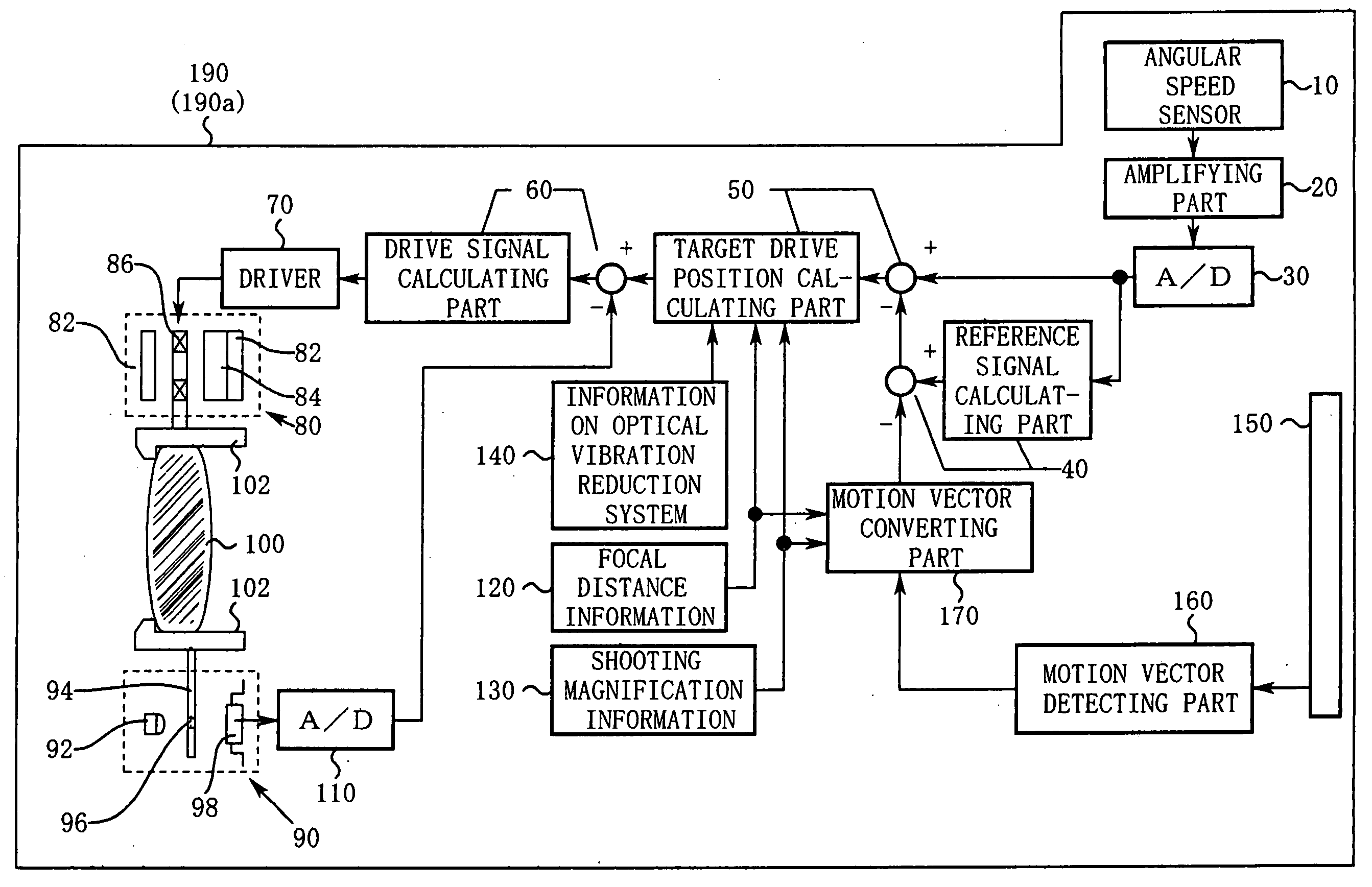
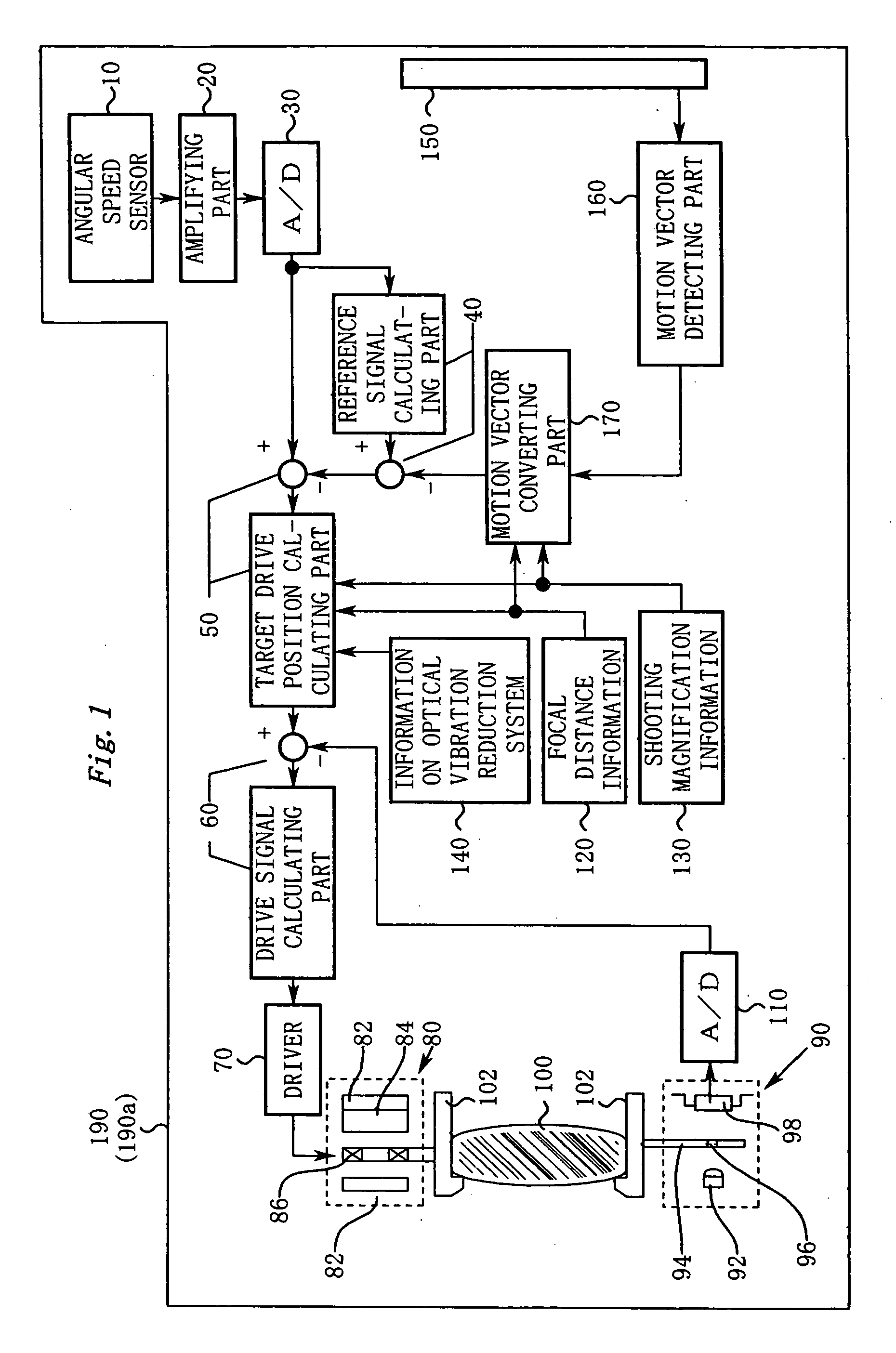
FIG. 1 shows a schematic block diagram of a camera system 190 (including a shooting lens 190a) according to the first embodiment of the present invention. In reality, the camera system 190 reduces a vibration of an image in two axis directions, horizontal and vertical directions. However, for simplicity, in FIG. 1, a vibration reduction mechanism for one axis is shown.

Next, the structure of each part shown in FIG. 1 will be described.

An angular speed sensor 10 detects a vibration of the camera system 190 as an angular speed using Coriolis force. An amplifying part 20 amplifies an output of the angular speed sensor 10. In addition, a low-pass filter may be disposed to reduce a high frequency noise in the sensor output. An A / D converting part 30 converts an output of the amplifying part 20 into digital angular speed data.

A reference signal calculating part 40 extracts a low frequency component from the angular...

second embodiment

<<Second Embodiment>>

[Description of Structure of Second Embodiment]

FIG. 8 is a schematic diagram showing a camera system 290 (including a shooting lens 290a) according to a second embodiment of the present invention. FIG. 9 is a block diagram showing a principal structure of a vibration reduction control system.

Next, with reference to FIG. 8 and FIG. 9, the structure of each part of the camera system 290 will be described. For simplicity, description of structural parts that are in common with the first embodiment (FIG. 1) will be omitted.

First of all, a target drive position calculating part 50 (in detail, a part denoted by reference numeral 50a in FIG. 8) subtracts a reference signal from angular speed data so as to obtain an actual angular speed as a cause of a vibration of an image.

The target drive position calculating part 50 (in detail, a part denoted by reference numeral 50b in FIG. 8) converts the actual angular speed into a scale of the moving amount of a ...


PUM


Abstract

The invention includes a vibration reduction mechanism, a vibration detecting part, a reference signal generating part, a target drive position calculating part, and a driving part. The vibration reduction mechanism reduces a vibration of a subject image. The vibration detecting part outputs a vibration detection signal. The reference signal generating part estimates a reference signal of the vibration detection part. The target drive position calculating part obtains a vibration component from a difference between the vibration detection signal and the estimated reference signal to obtain a target position to which the vibration reduction mechanism is driven. The driving part controls the vibration reduction mechanism to follow the target position. Particularly, the reference signal generating part corrects the reference signal according to a motion signal obtained from a captured image. An accurate reference signal can be obtained by the correction, thereby improving the performance of the vibration reduction.

Description

CROSS REFERENCE TO RELATED APPLICATION This application is based upon and claims the benefit of priority from Japanese Patent Application Nos. 2003-279688 and 2003-280097, both filed on Jul. 25, 2003, the entire contents of which are incorporated herein by reference. BACKGROUND OF THE INVENTION 1. Field of the Invention The present invention relates to a shooting lens for reducing a vibration of an image of a subject and a camera system therefor. 2. Description of the Related Art There has been a known technique for driving a vibration reduction mechanism to reduce a vibration of an image of a subject due to a hand vibration or the like. Such a known technique includes a vibration reduction mechanism (such as an optical vibration reduction system or the like) and an angular speed sensor. The angular speed sensor detects vibration of a shooting lens and of a camera. The shooting lens decides, from the angular speed, the position of the vibration reduction mechanism to eliminate ...

Claims


Application Information

Patent Timeline
IPC IPC(8): H04N5/232
CPCH04N5/23248H04N5/23287H04N5/23258H04N5/23254H04N23/68H04N23/6811H04N23/6812H04N23/687
Inventor TOMITA, HIROYUKIUSUI, KAZUTOSHIMATSUMOTO, TSUYOSHI
Owner NIKON CORP
Why Eureka
Try Eureka