Positioning stage

Inactive Publication Date: 2005-01-27
IBM CORP
View PDF7 Cites 18 Cited by
  • Summary
  • Abstract
  • Description
  • Claims
  • Application Information

AI Technical Summary

Benefits of technology

[0006] A positioning stage of the invention has a structure in which a joint is fixed to a base or a first table by a clutch and a table position is finely adjusted by moving the table relative to the joint. It enables a smaller fine-adjustment mechanism. Therefore, the positioning stage of the invention can be constructed so as to be lightweight and compact even if it is large-sized. In other words, the positioning stage according to the invention is capable of easy fine adjustment of an object position and of coping with a demand for a larger positioning stage. For example, a positioning stage with sides of approximately 1 meter can be constructed to be lightweight and compact.

Problems solved by technology

Furthermore, it is not easy to control fluids.
However, the microscope stage is designed for minute objects, so that it is not easy to directly apply its structure for a larger stage.

Method used


Image

  • Positioning stage
  • Positioning stage
  • Positioning stage

Examples


Embodiment Construction

[0023] An embodiment of a positioning stage in accordance with the invention will now be explained in detail with reference to the accompanying drawings.

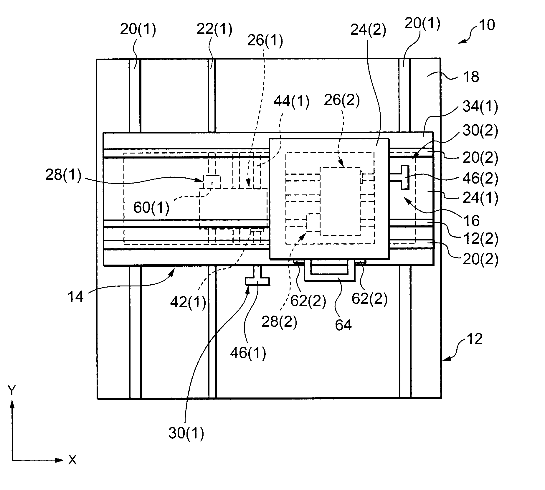
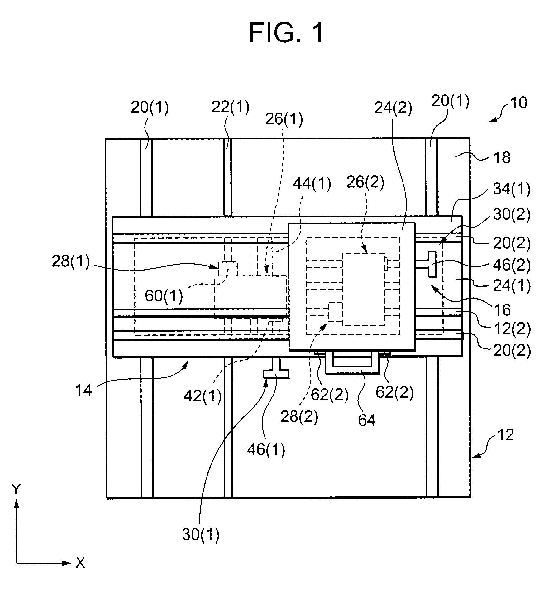
[0024] Referring to FIG. 1 through FIG. 4, a positioning stage 10 in accordance with the invention is an apparatus for positioning objects in two-dimensional directions (XY directions). The positioning stage 10 is constructed of a base 12, a Y-axis direction positioning means 14, and an X-axis direction positioning means 16.

[0025] The base 12 has two first rails 20(1) that are mounted on a top surface 18 such that they are parallel to the Y-axis. The base 12 also has a plate 22(1) mounted on the top surface 18 such that it is parallel to the first rails 20(1).

[0026] The Y-axis direction positioning means 14 moves and positions objects in the Y-axis direction. The Y-axis direction positioning means 14 has a first table 24(1), a first joint 26(1), a first clutch 28(1), and a first forcibly-moving means 30(1). The first joint 26(1) ...


PUM


Abstract

A positioning stage 10 is constructed of a base 12, a Y-axis direction positioning means 14, and an X-axis direction positioning means 16. The Y-axis direction positioning means 14 is a means for moving an object in a Y-axis direction to position it. The Y-axis direction positioning means 14 is provided with a first table 24(1), a first joint 26(1), a first clutch 28(1), and a first forcibly-moving means 30(1). An X-axis direction positioning means 16 is provided with a second table 24(2), a second joint 26(2), a second clutch 28(2), and a second forcibly-moving means 30(2).

Description

BACKGROUND OF INVENTION [0001] The invention relates to a positioning stage used for observation, inspection, measurement, or production. [0002] In the past, a positioning stage for positioning an object for manufacture or the like of electronic equipment has been used. Japanese Unexamined Patent Application Publication No. S60-39044 discloses a positioning stage wherein an XY table apparatus in which a table is moved in X-axis and Y-axis directions by a screw mechanism. The XY table apparatus permits fine adjustment of the position of an object by jogging a fine adjusting member to which an object to be positioned is installed while supporting the fine adjusting member with a fluid. However, a large XY table apparatus used for large objects is required to be equipped with a large-scale fluid controller. Furthermore, it is not easy to control fluids. Japanese Unexamined Patent Application Publication No. H11-95123 discloses another positioning stage comprising a microscope stage for...

Claims


Application Information

Patent Timeline
IPC IPC(8): B23Q1/00G12B5/00G02B21/26
CPCG02B21/26
Inventor KIMURA, HIDEO
Owner IBM CORP
Why Eureka
Try Eureka