Holder for arm-mounted medical imaging probe

Inactive Publication Date: 2010-12-28
WELLAN MEDICAL SOLUTIONS
View PDF5 Cites 1 Cited by
  • Summary
  • Abstract
  • Description
  • Claims
  • Application Information

AI Technical Summary

Benefits of technology

[0018]This invention overcomes the disadvantages of the prior art by providing a holder for an imaging probe that attaches to a flexible arm, which accommodates a variety of sizes and shapes of probes, is lightweight and allows for easy attachment and detachment of probes. The holder has a pleasing and ergonomic shape and accommodates a variety of gripping surfaces that can include customized decorations and / or sculpting. In an illustrative embodiment, the probe holder includes a pair of confronting clamp plates that include clamping jaws for holding a probe or other item at their distal end. The distal ends of the plates can include elastomeric pads that conform to the shape of the probe being griped. The proximal end of each plate includes a hemispherical well that engages a ball on a base member to define a highly flexible ball joint. This ball joint allows for easy fine adjustment of probe alignment, rotation and tilting, while frictionally maintaining the set position. The base member is attached to a flexible arm that can be constructed from a plurality of hollow, ball-and-socket segments. The plates are biased toward each other, and toward the ball joint by one or more elastic bands that surround the exterior of the plates near their proximal ends generally ahead of the diametral axis of the ball. The plates are aligned against skew using a T-shaped member that engages a conforming slot on each plate interior surface. A variety of alternate alignment and movement-limiting components can be employed. The T-shaped member also acts to provide a proximal backstop to the further proximal movement of the probe, helping to ensure that its head remains exposed for engagement with a target area on a body.
[0019]The probe holder can include an undercut surface to accommodate removable gripping surfaces that can include logos or ergonomic sculpting that facilitates positive grip by a user. The geometry of the ball, bands and plates allows the plates to expand to accommodate probes of differing sizes and thicknesses. The thicker (and more weighty) the probe, the greater the pressure bearing upon the ball by the wells based upon leverage. This aids in applying proportionally greater holding friction to the ball that assists in maintaining the set position of a heavier probe.
[0020]The plates can be limited in movement toward and away from each other so that the jaws remain open when in a resting state (without attached probe), but at a spacing that is smaller than the minimum expected probe thickness. In this manner, the probe may be inserted, one-handed, into the holder by a practitioner. This further enhances the hands-free nature of the holder and underlying flexible arm.

Problems solved by technology

The major challenge for the clinician performing nerve blocks is related to finding the nerve of interest.
Because anatomy is variable, this technique results in significant failure rates, multiple needle passes, and significant potential for pain and injury to the nerve and adjacent structures.
Once a satisfactory image of the structure is acquired, subtle movements of the hand holding the probe may result in degradation of the image, requiring a repositioning of the probe.
In addition to anatomical differences between patients, traditional landmark and nerve stimulator techniques can produce incomplete blockage of pain for patients because the drugs administered may not completely perfuse the nerves.
Too much pressure tends to distort the underlying tissues, making for an inaccurate image and pinching of internal tissues that may lead to misdirection of the needle.
Too little pressure yields a bad image.
The single-practitioner approach is rarely used in practice, both due to quality and safety concerns and also to prevailing medical practice rules and custom.
If the probe's face is skewed to the target surface, the image will be inferior or unreadable.
While the arm structure is technically capable of movement in each of the desired degrees of freedom, the segments tend to drag against each other frictionally when the arm is biased in a direction.
This creates a situation where the practitioner tends to overshoot the desired target location.
Thus, in practice, using the arm to manipulate each of alignment, rotation and tilt can prove laborious and inaccurate.

Method used


Image

  • Holder for arm-mounted medical imaging probe
  • Holder for arm-mounted medical imaging probe
  • Holder for arm-mounted medical imaging probe

Examples


Embodiment Construction

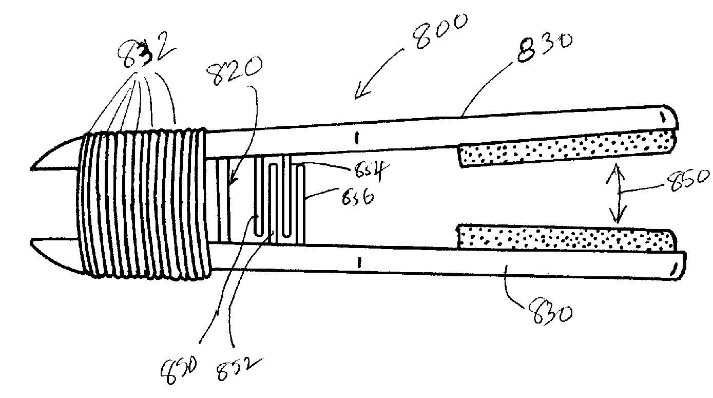
[0039]FIGS. 5 and 6, detail a probe mount 500 in accordance with an illustrative embodiment of this invention. The mount 500 is attached to the distal end 502 of a flexible arm 504 that is constructed from a series of interconnected, plastic segments 506 typically in accordance with the above-incorporated U.S. patent application Ser. No. 11 / 338,270, entitled BIOMEDICAL POSITIONING AND STABILIZATION SYSTEM. Alternatively, attachment of the probe mount to any type of flexible, semi-flexible or swiveling arm is expressly contemplated. The distal end 502 of the arm 504 includes a threaded end 510, which includes a male thread in this embodiment. The end 510 engages a female base 512 at the proximal end of the probe holder 500. The base 512 is constructed from polymer for strength and lightness of weight. The base includes a ball end 514, which is described further below. Briefly, the ball 514 engages a pair of holder clamp plates 530 that are identical or similar in this embodiment. The...


PUM


Abstract

This invention provides a holder for an imaging probe that attaches to a flexible arm, which accommodates a variety of sizes and shapes of probes, is lightweight and allows for easy attachment and detachment of probes. The probe holder includes a pair of confronting clamp plates that include clamping jaws for holding a probe or other item at their distal end. The distal ends of the plates can include elastomeric pads that conform to the shape of the probe being gripped. The proximal end of each plate includes a hemispherical well that engages a ball on a base member to define a highly flexible ball joint. This ball joint allows for easy fine adjustment of probe alignment, rotation and tilting, while frictionally maintaining the set position. A variety of alternate alignment and movement-limiting components can be employed.

Description

RELATED APPLICATION[0001]This application claims the benefit of U.S. Provisional Application No. 60 / 851,351, entitled HOLDER FOR ARM-MOUNTED MEDICAL IMAGING PROBE, by Katherine M. Hickey, et al., filed Oct. 12, 2006, the teachings of which are expressly incorporated herein by reference.BACKGROUND OF THE INVENTION[0002]1. Field of the Invention[0003]The invention relates to medical devices and, in particular, to a device for positioning and stabilizing diagnostic or therapeutic devices used in medical procedures.[0004]2. Background Information[0005]In clinical practice, there are many different procedures utilized for various diagnostic, therapeutic, monitoring, or guidance applications. These are typically conducted by a highly skilled operator who relies heavily on the ability to simultaneously perform multiple tasks, such as viewing a monitor while positioning a probe or dissecting tissue while exerting separation force upon the walls of an incision. Examples of such medical tasks...

Claims


Application Information

Patent Timeline
IPC IPC(8): E04G3/00
CPCA61B19/0256A61B19/26B25B9/00A61B90/50A61B50/20
Inventor HICKEY, KATHERINE M.GJERDE, AARON M.BLECK, JAMES H.SCENNA, LESLIE
Owner WELLAN MEDICAL SOLUTIONS
Why Eureka
Try Eureka