Internal combustion engine

Active Publication Date: 2006-05-23
ANDREAS STIHL AG & CO KG
View PDF5 Cites 3 Cited by
  • Summary
  • Abstract
  • Description
  • Claims
  • Application Information

AI Technical Summary

Benefits of technology

[0019]Thus, pursuant to the present application, the stop element, which establishes the idling position of the throttle element, forms a switch with an abutment that is connected with the throttle shaft. In the idling position of the throttle element, the switch is actuated, so that the idling position is reliably determined. During opening of the throttle element, in other words when the throttle shaft is rotated, the abutment is released from the stop element, so that the switch is opened. Since the stop element itself establishes the idling position of the throttle element, alteration of the idling position does not necessitate a readjustment. Since with conventional internal combustion engines the abutment and the stop element are generally already present, no additional devices are necessary for determining the idling position. The idling position can thus be reliably determined in a simple manner.
[0020]The throttle element is advantageously the butterfly valve of the carburetor. The stop element is, in particular, an idling screw. In this connection, the idling screw expediently has a conical portion that cooperates with the abutment. By means of the conical portion of the idling screw, the idling position of the throttle element can be easily and finely adjusted.
[0024]The signal produced by the switch expediently forms the input signal for a performance characteristic ignition. In this connection, the ignition timing is regulated, for example, as a function of temperatures and lambda values. Different performance characteristics are utilized during idling, partial load and in full load. In this connection, the signal of the switch serves, together with other parameters, for the selection of a performance characteristic. The signal produced by the switch advantageously activates the brake for a tool driven by the internal combustion engine, and / or switches the brake so as to be free. In this way, one can ensure that the tool does not run during idling. In this connection, the signal generated during closing of the switch serves for the activation of the brake, and the signal generated during the opening of the switch serves for freeing the brake, so that during idling the tool does not run, but is operated when the idling position is left.

Problems solved by technology

Such a device is structurally complicated.

Method used


Image

  • Internal combustion engine
  • Internal combustion engine
  • Internal combustion engine

Examples


Embodiment Construction

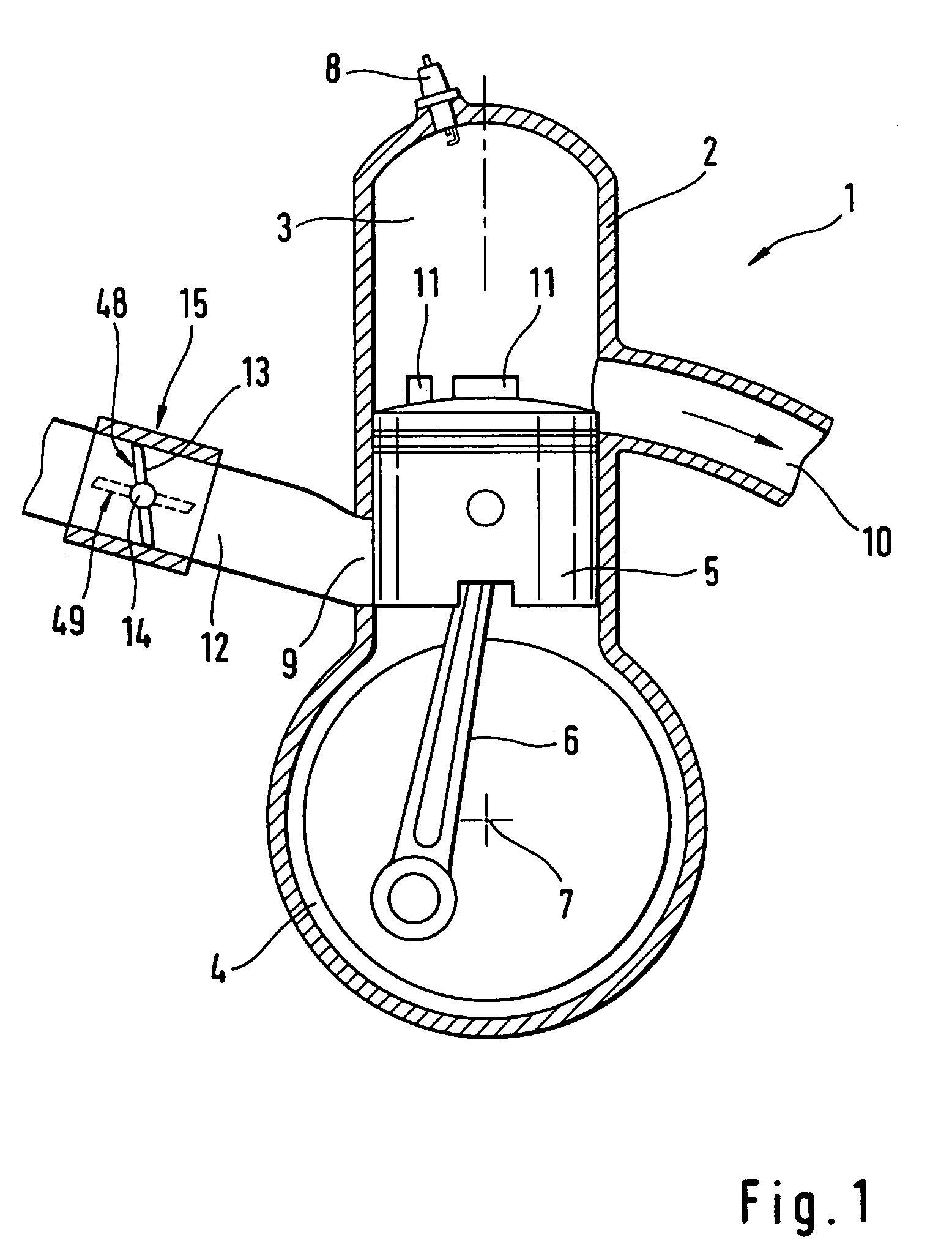
[0026]Referring now to the drawings in detail, the internal combustion engine 1 that is schematically illustrated in FIG. 1 is embodied as a two-cycle engine. The engine has a cylinder 2, in which is formed a combustion chamber 3. In prescribed positions of a piston 5, the combustion chamber 3 is connected with a crankcase 4. The piston 5 is reciprocably mounted in the cylinder 2 and, via a connecting rod 6, drives the crankshaft 7 that is mounted in the crankcase 4. The internal combustion engine 1 has an intake channel 12 that supplies a fuel / air mixture to the crankcase 4, via an inlet 9, in prescribed positions of the piston 5. The fuel / air mixture is prepared in a carburetor 15. Pivotably mounted in the carburetor 15 is a throttle element, namely a throttle or butterfly valve 13, via a throttle shaft 14. The butterfly valve 13 is movable between the idling position 48, in which it substantially closes off the intake channel 12, and the full-load position 49, which is illustrate...


PUM


Abstract

An internal combustion engine is provided, and has a throttle element mounted in the intake channel of the engine so as to be pivotable, via a throttle shaft, between an idling position and a full-load position. An abutment is fixedly connected with the throttle shaft. In the idling position, the abutment rests against a stop element that is fixed in position on the intake channel. The stop element is adjustable and establishes the idling position of the throttle element. The abutment forms, with the stop element, a switch that is actuated in the idling position of the throttle element.

Description

BACKGROUND OF THE INVENTION[0001]The present invention relates to an internal combustion engine.[0002]DE 75 19 322 U1 discloses the arrangement of a throttle element in the intake channel of an internal combustion engine. Connected with the throttle element is a lever that in the idling position rests against an idling screw. The idling position of the throttle element can be established via the idling screw.[0003]With internal combustion engines, the ignition timing or time point is adapted to the respective load condition. Thus, for the control of the ignition timing it is necessary to recognize the idling position of the throttle element. With DE 75 19 322 U1, to establish the idling position a pneumatic device is provided that receives the pressure before and after the throttle element and that additionally takes into consideration the position of the gas pedal. Such a device is structurally complicated. By shifting the idling screw, and hence the position of the throttle elemen...

Claims


Application Information

Patent Timeline
IPC IPC(8): F02D41/16G01M15/00F02D9/00F02B63/02F02B75/02F02D9/02F02D9/10F02D11/04F02M3/07
CPCF02D9/1065F02M3/07F02D11/04F02B63/02F02B2075/025F02D2009/0208F02D2009/0296
Inventor FRANK, THOMASHAGELE, ANDREASABOU-ALY, MOHAMEDSCHIEBER, EBERHARD
Owner ANDREAS STIHL AG & CO KG
Why Eureka
Try Eureka