Expandable spinal implant

a spinal implant and expandable technology, applied in the field of expandable spinal implants, can solve the problems of limiting the range of motion of the spine, threatening the critical elements, and affecting the function of the spine,

Active Publication Date: 2005-01-27
RESSPOND SPINAL SYST
View PDF18 Cites 127 Cited by
  • Summary
  • Abstract
  • Description
  • Claims
  • Application Information

AI Technical Summary

Problems solved by technology

Genetic or developmental irregularities, trauma, chronic stress, tumors, and disease, however, can result in spinal pathologies which either limit this range of mot...

Method used


Image

  • Expandable spinal implant
  • Expandable spinal implant
  • Expandable spinal implant

Examples


Embodiment Construction

[0032] The following description of various embodiments is merely exemplary in nature and is in no way intended to limit the invention, its application, or uses.

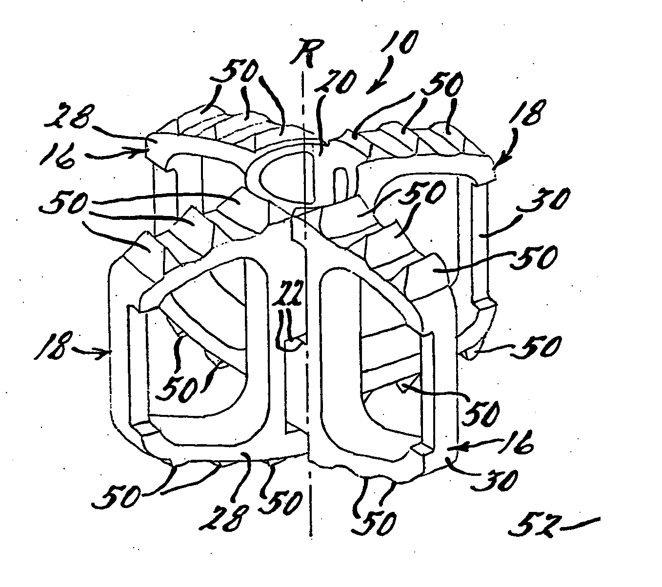
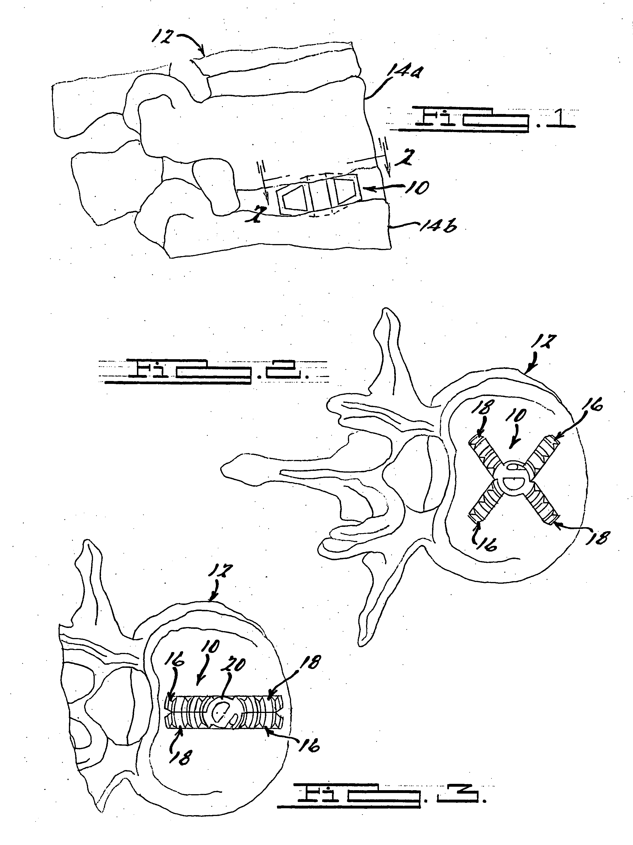
[0033] With initial reference to FIG. 1 and FIG. 2, an exemplary spinal implant constructed in accordance with the present teachings is illustrated and generally identified at reference number 10. The spinal implant 10 is shown operatively associated with a human spinal column 12. More specifically, the spinal implant 10 is shown positioned between a first vertebra 14a and a second vertebra 14b to stabilize the spine 12.

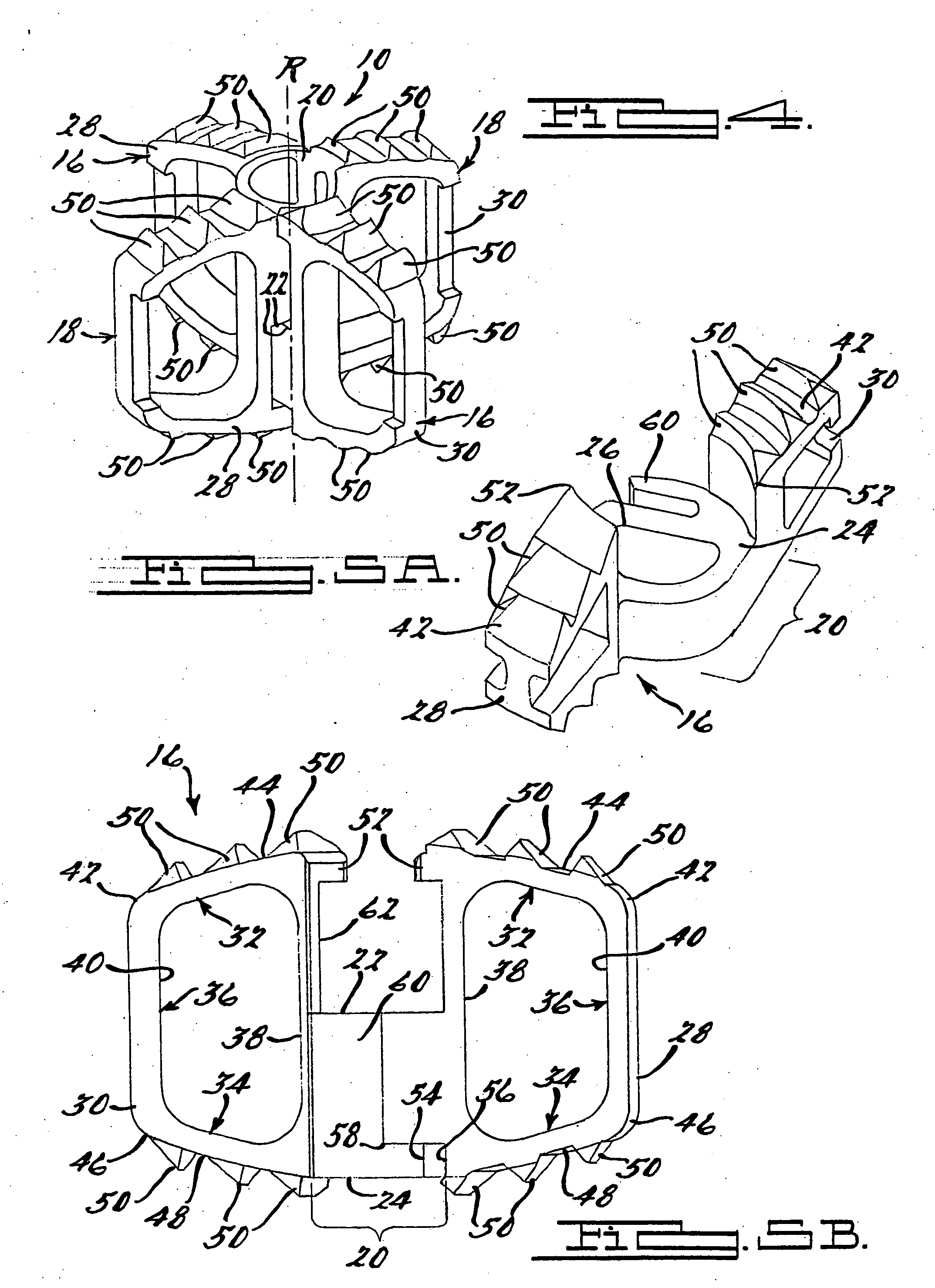
[0034] With continued reference to the environmental views of FIGS. 1 and 2 and additional reference to FIGS. 3 through 7, the spinal implant 10 of the present invention will be addressed in detail. The spinal implant 10 is illustrated to generally include a first member or first elongated member 16 and a second member or second elongated member 18. As will become more apparent below, the first elongated me...


PUM


Abstract

An expandable spinal implant including a first member and a second member. The first member has first and second arms. The first and second arms of the first member both including an upper face partially defining an upper contact area of the implant and a lower face partially defining a lower contact surface of the implant. The second member has first and second arms that both include an upper face partially defining an upper contact area of the implant and a lower face partially defining a lower contact surface of the implant. The first and second members are pivotally coupled to each other for relative movement about a rotation axis between a closed position for inserting the implant into a spine and an expanded position for providing structural support to the spine. The rotation axis extends generally perpendicular to the upper and lower contact surfaces.

Description

CROSS-REFERENCE TO RELATED APPLICATIONS [0001] This application claims the benefit of U.S. Provisional Application No. 60 / 489,731, filed on Jul. 23, 2003. The disclosure of the above application is incorporated herein by reference.BACKGROUND OF THE INVENTION [0002] The spinal column is a highly complex structure which houses and protects critical elements of the nervous system. In spite of these complexities, the spinal column is a highly flexible structure, capable of a high degree of curvature and twist through a wide range motion. Genetic or developmental irregularities, trauma, chronic stress, tumors, and disease, however, can result in spinal pathologies which either limit this range of motion, or threaten the critical elements of the nervous system housed within the spinal column. [0003] In various orthopedic surgical procedures, it is necessary to stabilize portions of a spinal column relative to one another. This need is typically a result of disease, damage or congenital de...

Claims


Application Information

Patent Timeline
IPC IPC(8): A61F2/00A61F2/02A61F2/28A61F2/30A61F2/44A61F2/46
CPCA61F2/28A61F2310/00359A61F2/4455A61F2002/30179A61F2002/30433A61F2002/30471A61F2002/30476A61F2002/30505A61F2002/30507A61F2002/30538A61F2002/30579A61F2002/30616A61F2002/30772A61F2002/30846A61F2002/30975A61F2002/448A61F2002/4629A61F2220/0025A61F2220/0041A61F2220/0091A61F2230/0058A61F2250/0006A61F2310/00023A61F2/442A61F2002/30845
Inventor MALBERG, MARC I.SHAH, GRETCHEN DOUGHERTYFERREIRA, RUI J.
Owner RESSPOND SPINAL SYST
Why Eureka
Try Eureka