
Method, network element, and terminal device for making data packets

a terminal device and data packet technology, applied in the field of method, network element, and terminal device for making data packets, can solve the problems of different delays in packets inside the network, network operator cannot guarantee the continuous availability of nbr,

Inactive Publication Date: 2005-01-27
NOKIA SOLUTIONS & NETWORKS OY
View PDF7 Cites 145 Cited by
  • Summary
  • Abstract
  • Description
  • Claims
  • Application Information

AI Technical Summary

Benefits of technology

[0030] It is further preferred that the importance marking is generated by an end-user input to said terminal device. Thus, the marking of the data packets with the importance marking can be controlled manually by an end-user, preferably assisted by a corresponding application interacting with the end-user. As a result the end-user is able to give certain data packets a higher priority.
[0032] According to a further preferred embodiment a data packet received from an individual terminal device is marked prior transmission through said network with an individual priority information depending on the respective application having generated said packet. In a corresponding preferred terminal device the importance marking generating means are generating an importance marking depending on an individual application being allocated to a current data packet. Thus, it is possible to treat in the network domain each application individually with an application individual priority information. Thus, the flexibility of the system is further increased.

Problems solved by technology

Thus, packets may encounter different delays inside the network caused e.g. by variation in occupancy levels of queues inside the routers.
Due to the simplicity of SIMA the network operator does not guarantee the continuous availability of NBR.
Though the SIMA model as being described in U.S. Pat. No. 6,047,326 and U.S. Pat. No. 6,081,505 has been proved to be efficient and quite flexible, it has some limitations.

Method used


Image

  • Method, network element, and terminal device for making data packets
  • Method, network element, and terminal device for making data packets
  • Method, network element, and terminal device for making data packets

Examples


Embodiment Construction

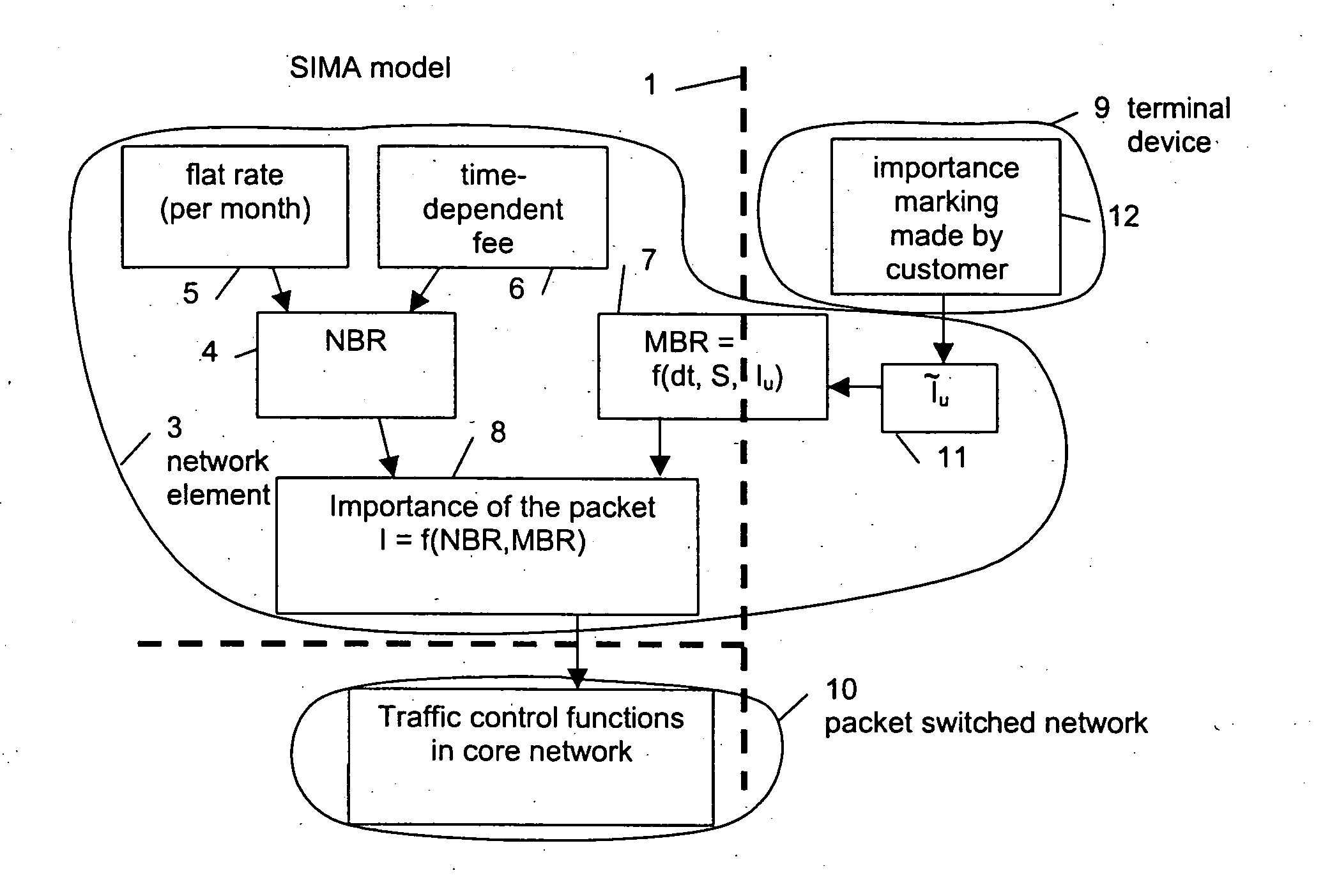
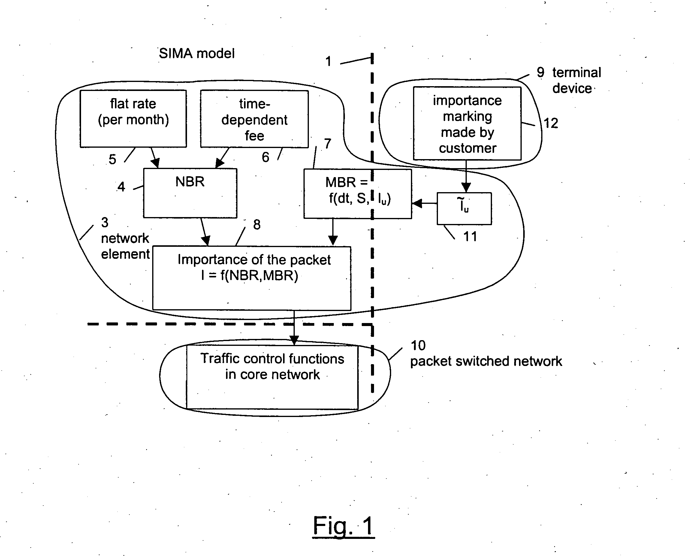
[0041]FIG. 1 shows a schematic diagram of a system for marking data packets according to a preferred embodiment of the present invention. FIG. 1 indicates both, prior art components of such a system as well as new components, both forming a preferred embodiment of the present invention. Prior art components are shown on the left side of a vertical dashed line 1 which is divided by a horizontal dashed line 2 into an upper left system part and a lower left system part. The upper left system part indicates the SIMA model according to U.S. Pat. No. 6,047,326 which is incorporated herein by reference. The lower left system part indicates the traffic control functions in the core network according to U.S. Pat. No. 6,081,505 which is incorporated herein by reference as well.

[0042] The packet marking system according to U.S. Pat. No. 6,047,326 comprises a network element 3 comprising a NBR determining unit 4 for determining a NBR. This NBR is for example determined based on a per month fla...


PUM


Abstract

The present invention relates to a method and a network element 3 for marking data packets to be transmitted in a packet switched network 10 with a priority information I, said packets being treated in said network 10 according to said priority information I. The priority information I is determined depending on a nominal bit rate NBR allocated to a certain service connection and a momentary bit rate MBR of said connection that is calculated depending on an importance marking IU contained in a received data packet indicating an importance level of said data packet. Thus, the nominal bit rate NBR allocated to an end-user can be shared between a plurality of applications with different characteristics in order to give certain applications a higher priority than other applications. The present invention relates to a corresponding terminal device 9 to be used with such a network element 3.

Description

FIELD OF THE INVENTION [0001] The present invention relates to a method and a network element for marking data packets to be transmitted in a packet switched network with a priority information, wherein that packets are treated in that network according to the priority information. Furthermore, the invention relates to a terminal device for generating corresponding data packets to be attached with said priority information by means of such network element by using such a method. BACKGROUND OF THE INVENTION [0002] In common communication networks, in particular in mobile communication networks two main techniques for a data transmission are used: circuit switched data transmission and packet switched data transmission. [0003] In the circuit switched domain a network establishes a service connection for data transmission by allocating a (radio) channel to a terminal, e.g. a mobile station, when a network host or service provider intends to transmit data via the network. Then data is t...

Claims


Application Information

Patent Timeline
Patent Type & Authority Applications(United States)
IPC IPC(8): H04L12/801H04L12/851
CPCH04L47/2408H04L47/10
Inventor KILKKI, KALEVI
Owner NOKIA SOLUTIONS & NETWORKS OY
Learn More