Laser level

a laser level and leveling technology, applied in the field of hand tools, can solve the problems of reducing the level accuracy by an appreciable amount, affecting the accuracy of the level, so as to achieve control and precision

Inactive Publication Date: 2005-02-03
OLYMPIA GROUP
View PDF48 Cites 58 Cited by
  • Summary
  • Abstract
  • Description
  • Claims
  • Application Information

AI Technical Summary

Benefits of technology

[0013] Embodiments of the present invention generally relate to an improved laser level. The laser level includes any combination of an anchor assembly, a suction assembly, or a magnet to be used for attaching the laser level to a surface. An adjustment assembly provides control and precision by allowing leveling or plumbing of the laser level after it attaches to the surface and by converting a relatively large rotation of an adjustment handle into a finer leveling adjustment of the laser level. In an embodiment, the laser level attaches to an auxiliary base that allows leveling of the laser level in two perpendicular planes and allows the laser level to attach to a tripod for use horizontally, vertically, and angles in between. In an embodiment, a rotary part allows selection from multiple lenses the one appropriate lens for the desired task.

Problems solved by technology

However, providing the sliding ability requires clearance in the lens assembly that reduces accuracy of the level by an appreciable amount.
When attempting to use a lens that provides the asymmetrical distribution to provide a line on an opposing wall, the line often fails to cover the entire wall due to the narrow dispersion of the asymmetrical distribution.
The lens for symmetrical distribution can display a line on the same wall as the device; however, the line is often faint and difficult to see since not all of the energy of the laser is directed at the intended surface.
Spikes used to attach the laser level to the wall can leave two or more unsightly and damaging holes in the wall after usage.
The mechanisms for extending the spikes are often quite difficult to operate since they are small and become recessed within an obstruction prior to complete extension of the spikes.
Additionally, inadvertent extension of the spikes can be dangerous and damaging to property.
Once attached to the wall, the device often lacks a mechanism to adjust the level of the device.
Even if adjustments are possible, a one to one relationship in the adjustment mechanism decreases the device's accuracy due to the lack of adjustment sensitivity.

Method used


Image

  • Laser level
  • Laser level
  • Laser level

Examples


Embodiment Construction

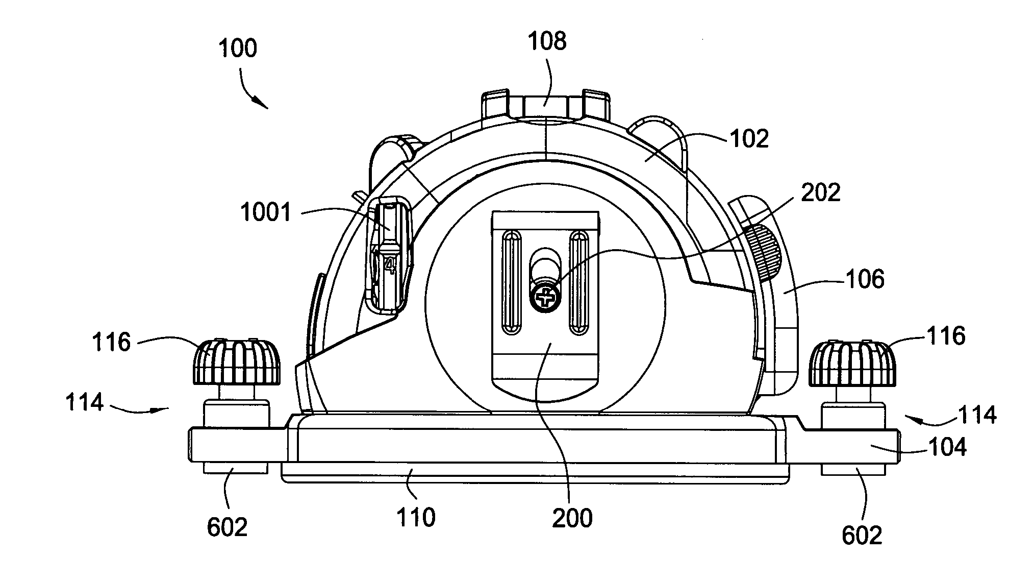
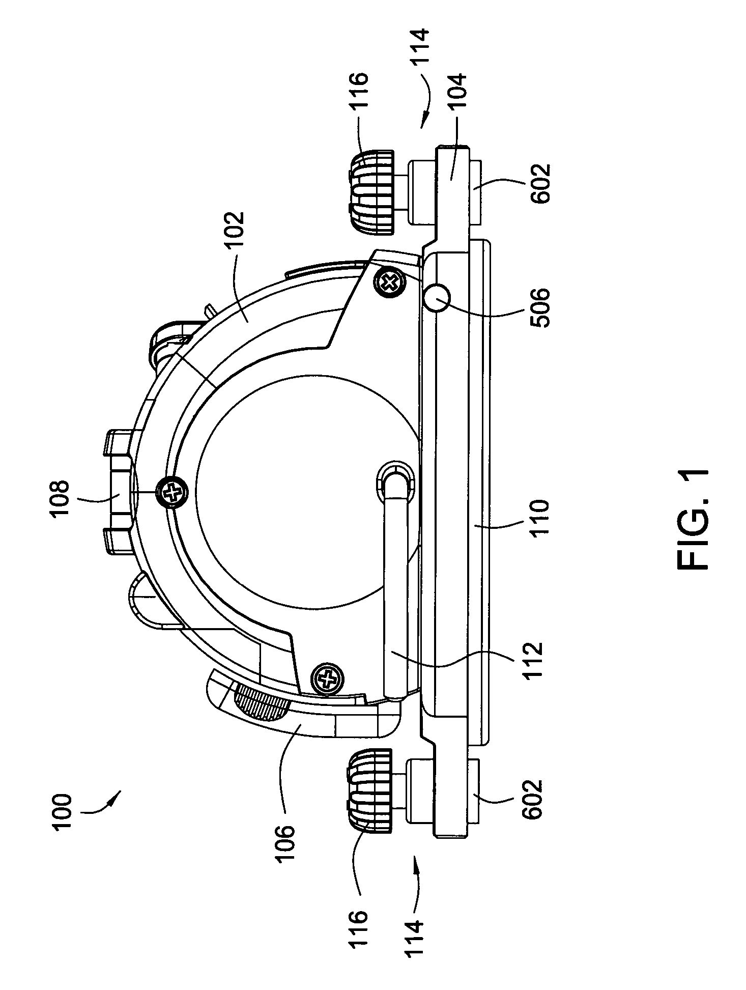
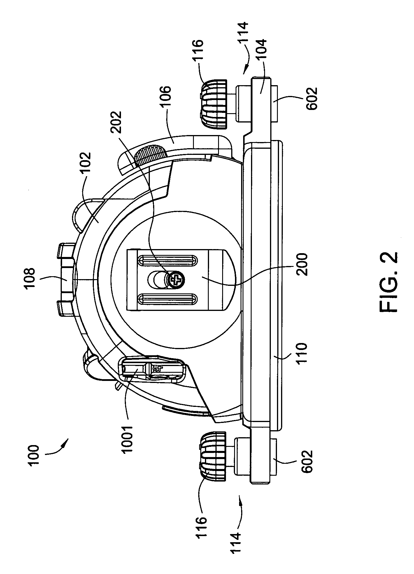
[0030] Embodiments of the present invention generally relate to an improved laser level 100. FIG. 1 presents the laser level 100 with an external housing 102 that covers some portions of the laser level located on top of a base 104. Also shown in FIG. 1 is an adjustment handle 106, a leveling vial 108, two anchoring assemblies 114 at each end of the laser level 100, and an elastomeric pad 110 proximate the base that is operated by a suction lever 112. The laser level 100 generally comprises the size and shape of a tape measure. FIG. 2 illustrates a back side of the laser level 100 with a belt clip 200 attached to the housing 102 by a screw 202. The belt clip 200 is similar to those on tape measures and provides convenient storage and transport of the laser level 100.

[0031] Referring to FIG. 1 and the section view shown in FIG. 8, the base 104 of the laser level 100 houses the two anchoring assemblies 114 that include retractable sharpened projections or spikes 300 that push into a ...


PUM


Abstract

The present invention provides an improved laser level. In one embodiment, the laser level comprises a housing having a base. The laser level further comprises any combination of an anchor assembly, a suction assembly, or a magnet to be used for attaching the laser level to a surface. An adjustment assembly provides control and precision by allowing leveling or plumbing of the laser level after it attaches to the surface and by converting a relatively large rotation of an adjustment handle into a finer leveling adjustment of the laser level. In an embodiment, the laser level attaches to an auxiliary base that allows leveling of the laser level in two perpendicular planes and allows the laser level to attach to a tripod for use horizontally, vertically, and angles in between. In an embodiment, a rotary part allows selection from multiple lenses the one appropriate lens for the desired task.

Description

CROSS-REFERENCE TO RELATED APPLICATIONS [0001] This application claims benefit of U.S. provisional patent application Ser. No. 60 / 491,787, filed Aug. 1, 2003, which is herein incorporated by reference.BACKGROUND OF THE INVENTION [0002] b 1. Field of the Invention [0003] The present invention relates to the field of hand tools. More particularly, embodiments of the present invention relate to a laser operated level. [0004] 2. Description of the Related Art [0005] During construction and remodeling projects, it is often desirable to install an object along a horizontal plane or line. Examples include the laying of a walkway, the erection of a wall, the installation of window frames, and the hanging of pictures on a wall. To accomplish a level or perpendicular installation, various tools have been used such as rulers, T-squares, and plumb bobs. It has also been known to employ an elongated bar that incorporates a liquid-holding vial, or “bubble vial.” The vial includes integral marks f...

Claims


Application Information

Patent Timeline
Patent Type & Authority Applications(United States)
IPC IPC(8): G01C5/00G01C9/06G01C15/00
CPCG01C15/002
Inventor WHEELER, THOMAS J.KHACHATOORIAN, ZAREH
Owner OLYMPIA GROUP
Why Eureka
Try Eureka