
Reel, recording tape cartridge and method of manufacturing the reel

a technology of reel gear and recording tape, which is applied in the direction of record information storage, magazine/cassette manufacturing apparatus, instruments, etc., can solve the problems of skewed through-holes, mutual axial centers of reel gear and uncentered reel gear, and achieve high precision and stably pulled ou

Inactive Publication Date: 2005-02-03
FUJIFILM HLDG CORP +1
View PDF11 Cites 9 Cited by
  • Summary
  • Abstract
  • Description
  • Claims
  • Application Information

AI Technical Summary

Benefits of technology

The present invention provides a reel with a hub where a reel gear and a through-hole can be precisely positioned. This allows for the stable pull-out of recording tape from the reel. The invention also provides a reel with a reference portion that simplifies the design and dimensional management of the reel, and prevents uncenteredness and slanting when the reel is rotatingly driven. The invention also includes a common mold that integrates the reel gear and hole portion forming portions, or the reel gear and reference portion forming portions, to achieve high precision in the alignment of the axial centers.

Problems solved by technology

In a recording tape cartridge disposed with such a reel, the design and dimensional evaluation of respective parts have been cumbersome because the dimensions of the respective parts have been determined on the basis of the virtual reference surface obtained by making the reel gear mesh with the drive gear.
However, in the configuration described in the specification of U.S. Pat. No. 6,273,352, there is the potential for the reel to become uncentered with respect to the rotating shaft because a slight backlash arises between the reel gear and the drive gear.
For this reason, there have been instances where the mutual axial centers of the reel gear and the through-hole end up becoming skewed due to (dependent on) positional skewing of the movable mold with respect to the fixed mold.

Method used


Image

  • Reel, recording tape cartridge and method of manufacturing the reel
  • Reel, recording tape cartridge and method of manufacturing the reel
  • Reel, recording tape cartridge and method of manufacturing the reel

Examples


Embodiment Construction

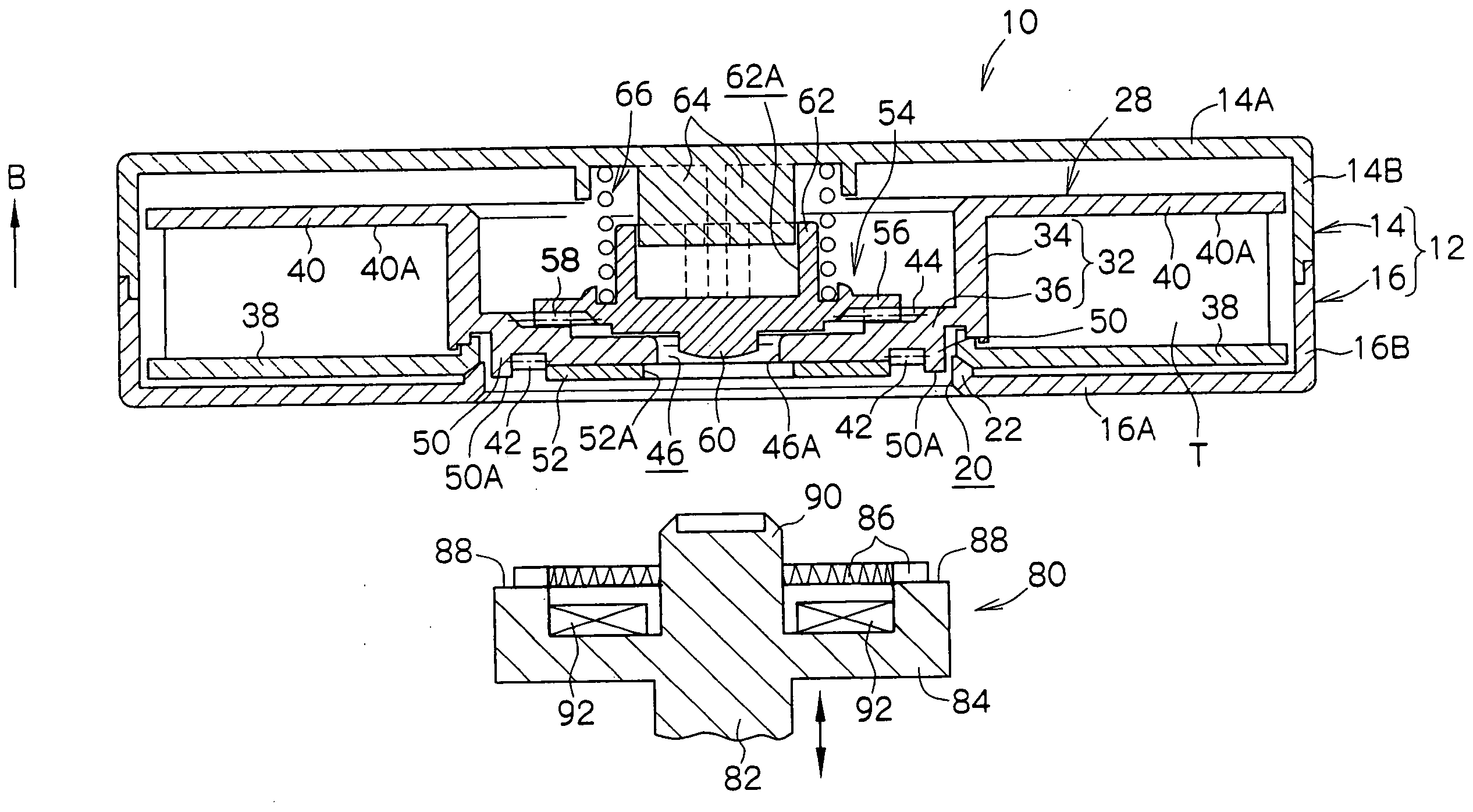
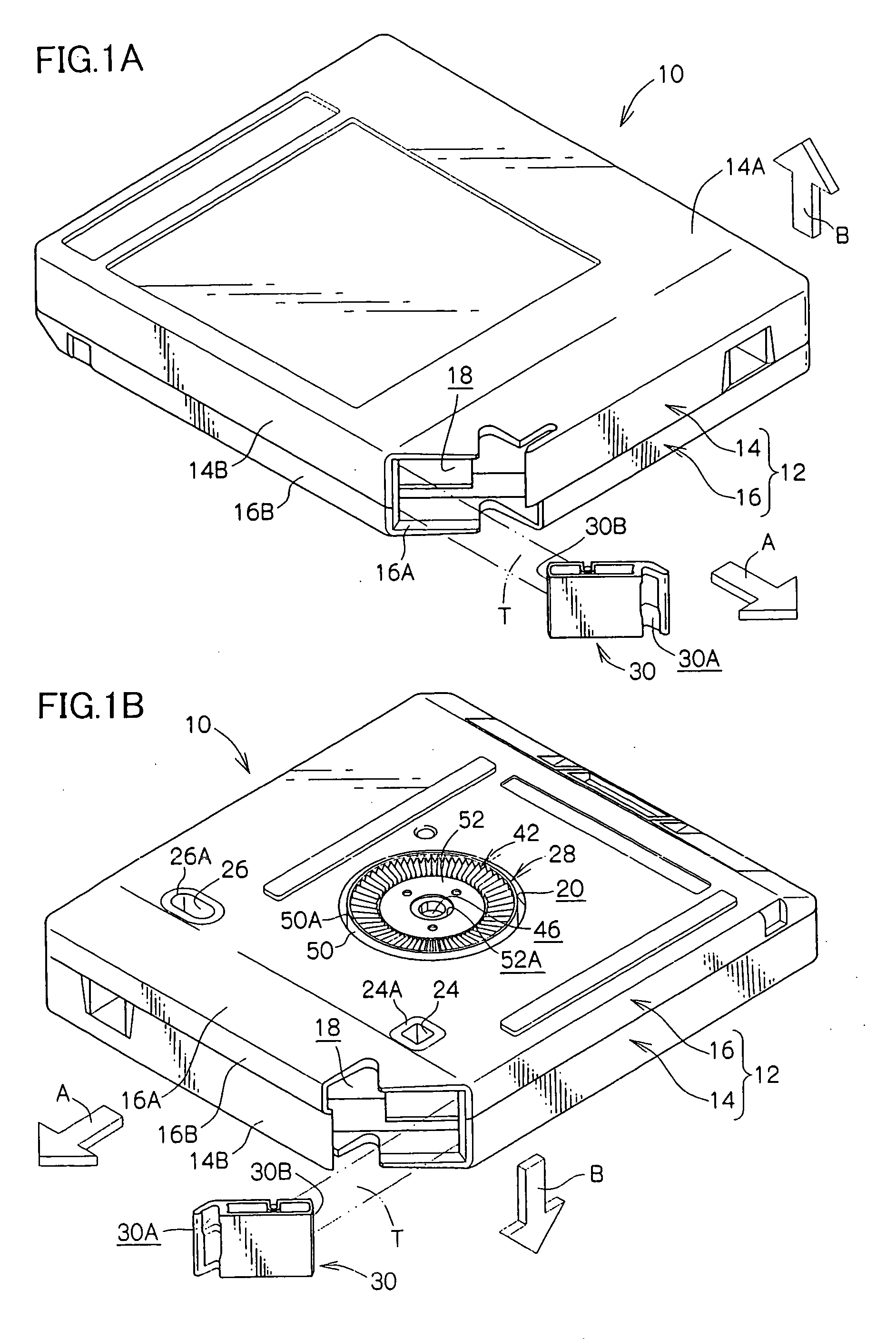
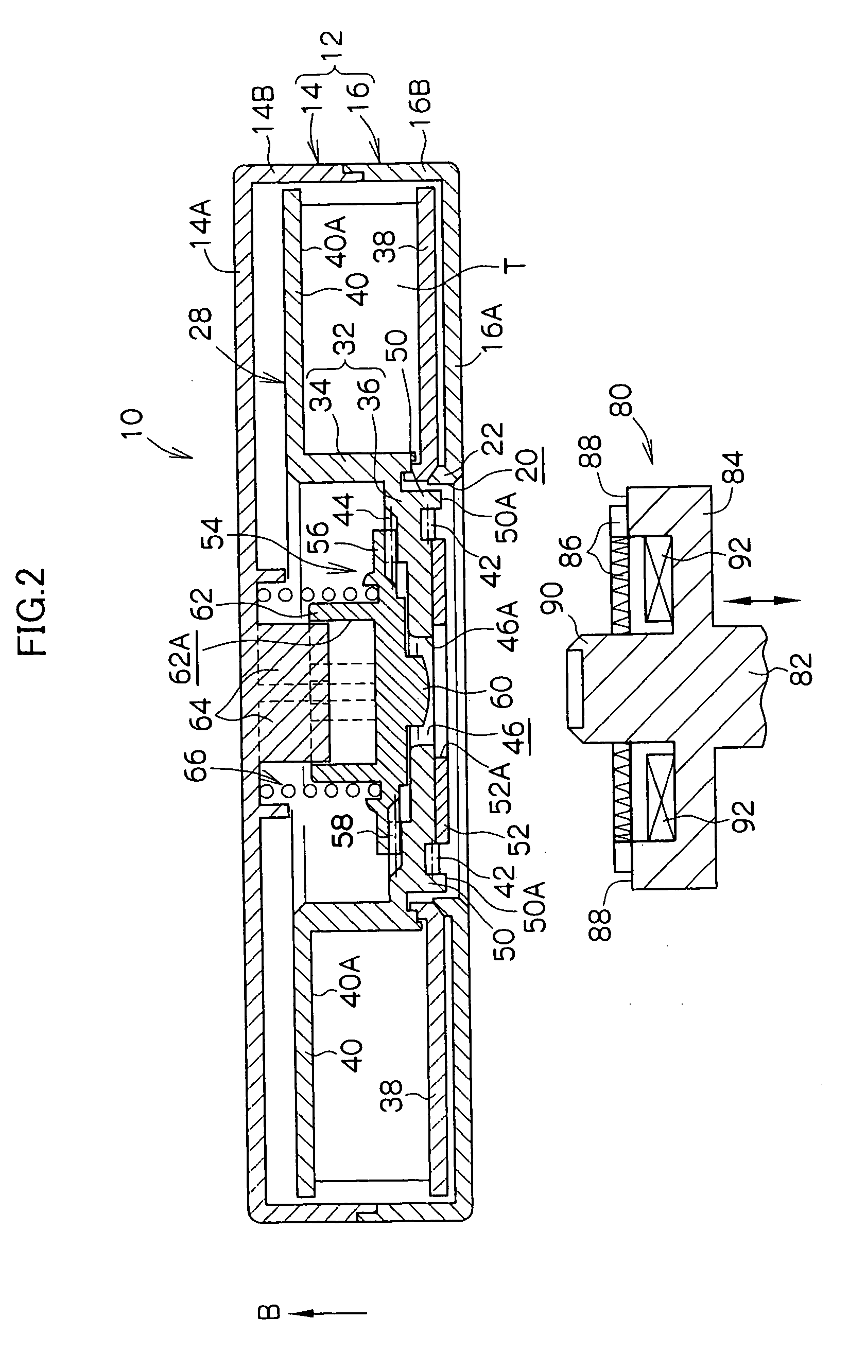
[0042] A recording tape cartridge 10 to which a reel 28 pertaining to an embodiment of the invention has been applied will be described on the basis of FIGS. 1A and 1B to FIG. 5.

[0043] (Overall Configuration of the Recording Tape Cartridge)

[0044]FIG. 1A is a perspective view of the recording tape cartridge 10 seen from diagonally above. FIG. 1B is a perspective view of the recording tape cartridge seen from diagonally below. FIGS. 2 and 3 are cross-sectional views of the recording tape cartridge 10. The arrow A appropriately shown in each drawing represents the direction in which the recording tape cartridge 10 is loaded in a drive device. For convenience of explanation, the side indicated by arrow A will be referred to as the front side, and the direction indicated by arrow B will be referred to as the top side.

[0045] As shown in these drawings, the recording tape cartridge 10 is disposed with a case 12. The case 12 is configured by joining together an upper case 14 and a lower ...


PUM

PropertyMeasurementUnit
lengthaaaaaaaaaa
lengthaaaaaaaaaa
draft angleaaaaaaaaaa

Abstract

A reel of a recording tape cartridge includes a reel hub formed in a bottomed cylindrical shape, an annular reel gear coaxially disposed at an outer surface of a bottom portion of the reel hub, and a through-hole the penetrates the axial center of the bottom portion and opens to an outer surface side of the bottom portion. The reel is resin-molded using a mold comprising a fixed mold, a movable mold and an insert. The reel gear and the through-hole are formed by a reel gear forming portion and a hole portion forming portion disposed in a single insert. As a result, the axial centers thereof are aligned with high precision.

Description

CROSS-REFERENCE TO RELATED APPLICATION [0001] This application claims priority under 35 USC 119 from Japanese Patent Application No. 2003-284011, the disclosure of which is incorporated by reference herein. BACKGROUND OF THE INVENTION [0002] 1. Field of the Invention [0003] The present invention relates to a reel wound with recording tape such as magnetic tape, a recording tape cartridge in which the reel is rotatably housed inside a case, and a method of manufacturing the reel. [0004] 2. Description of the Related Art [0005] Recording tape such as magnetic tape is used as an external recording medium for computers and the like. A so-called single-reel recording tape cartridge, whose housing space at the time of storage is small, in which a large amount of information can be recorded and in which a single reel wound with recording tape is rotatably housed inside a case, is used for the recording tape. [0006] In such a recording tape cartridge, a reel gear is annularly disposed at an...

Claims


Application Information

Patent Timeline
Patent Type & Authority Applications(United States)
IPC IPC(8): G11B23/107G11B23/04G11B23/113
CPCG11B23/043G11B23/113G11B23/107G11B23/044
Inventor HIRAGUCHI, KAZUO
Owner FUJIFILM HLDG CORP
Learn More