Sheet finisher, sheet processing apparatus, image forming system and methods for the same

a technology of image forming system and sheet processing apparatus, which is applied in the direction of electrographic process, instruments, transportation and packaging, etc., can solve the problems of inability to perform certain adjustments, and bad ejection of sheets

Inactive Publication Date: 2005-02-03
KONICA CORP
View PDF5 Cites 16 Cited by
  • Summary
  • Abstract
  • Description
  • Claims
  • Application Information

AI Technical Summary

Benefits of technology

[0024] Further, the sheet finisher may further comprise: a control section for controlling air blowing of the air-blowing member, and preferably, the control section controls to start the air blowing when a first sheet to which the predetermined processing is carried out is conveyed to the sheet placing member, and to stop the air blowing when the stapled sheets are ejected out from the sheet placing member after stapling is performed to the predetermined number of the sheets. Accordingly, the first sheet can be prevented from being adhered to the sheet placing member by being pressed on the sheet placing member by the blown air. Moreover, the control section may make an amount of air blowing according to the air-blowing member vary in accordance with the number of the sheets to which the predetermined processing is carried out, the sheets being placed sequentially on the sheet placing member.
[0028] According to the sheet finisher of the present invention, since the paired rollers are made to wait in a half-open state when the sheet is ejected from the sheet ejection section, buckling, wrinkle, tears or the like caused by the front end portion of the sheet in the ejection direction hitting the construction members of the sheet ejection section, such as paired rollers or the like, can be prevented from being generated. Further, after the front end portion of the sheet in the ejection direction has passed the nipping position of the paired rollers, the sheet conveyance is stopped temporarily, and thereafter, the paired rollers are made to press-contact with each other and the sheet is re-conveyed and ejected out of the finisher. Therefore, sag or the like in the sheet according to a slip between the paired rollers and the sheet, or the like, can be prevented from being generated. Particularly, in case that the conveyance member has a construction such that the conveyance member supports the rear end portion of the sheet in the ejection direction to convey and eject the sheet from the sheet ejection section, buckling, wrinkle, tears or the like of the sheet in the vicinity of the rear end portion of the sheet according to the conveyance member, which is moving forward, pushing the rear end portion of the sheet upward can be prevented from being generated. Therefore, the sheet will be certainly ejected out from the sheet ejection section.
[0030] In the sheet finisher, preferably, the control section further controls the conveyance member and the sheet ejection section to temporarily release the press-contact of the paired rollers during re-conveyance of the sheet, and after removing a sag of the sheet during the conveyance, make the paired rollers press-contact with each other again, and to eject the sheet out of the finisher by nipping the sheet. Accordingly, sag of the sheet ejected by the paired rollers is prevented from increasing, so that the sheet can be certainly ejected from the sheet ejection section.

Problems solved by technology

In the sheet finishers for performing Z-folding and stapling in the earlier technology, there are some problems as follows.
Therefore, skew is easily caused, so that there is a problem that a certain adjustment cannot be performed.
Therefore, there occurs a problem that a certain adjustment cannot be performed.
Thereby, the stack of sheets is difficult to be nipped by the rotating sheet ejection rollers, so that bad ejection of sheets is caused.

Method used


Image

  • Sheet finisher, sheet processing apparatus, image forming system and methods for the same
  • Sheet finisher, sheet processing apparatus, image forming system and methods for the same
  • Sheet finisher, sheet processing apparatus, image forming system and methods for the same

Examples


Embodiment Construction

[0074] Next, a sheet finisher (hereinafter, it is referred to as “finisher”) according to an embodiment of the present invention, and a sheet processing apparatus and image forming system comprising the finisher will be explained on the basis of drawings.

[0075] [Image Forming System]

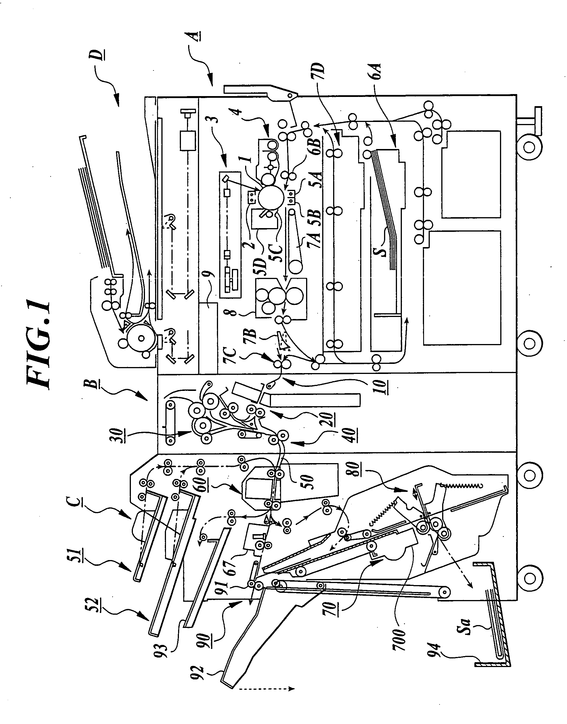
[0076]FIG. 1 is a whole construction view showing the image forming system comprising an image forming apparatus A, a first finisher (sheet folding apparatus) B, a second finisher (sheet finisher) C.

[0077] [Image Forming Apparatus]

[0078] The image forming apparatus A comprises an image forming section arranging a charging member 2, an image exposing section (image writing section) 3, a developing section 4, a transfer member 5A, a charge-removing member 5B, a separation claw 5C, and a cleaning member 5D around a rotating image carrying member 1. After charging is carried out uniformly to a surface of the image carrying member 1 by the charging member 2, a latent imager is formed by exposing and scannin...


PUM

PropertyMeasurementUnit
chargeaaaaaaaaaa
lengthaaaaaaaaaa
lengthaaaaaaaaaa

Abstract

A sheet finisher having a sheet placing member for placing and adjusting a predetermined number of sheets to which a predetermined processing is carried out thereon; a stapling member for stapling the predetermined number of adjusted sheets; and an air-blowing member arranged above the sheet placing member. The air-blowing member is operated to press each of the sheets against the sheet placing member by blowing air and adjust when each of the sheets to which the predetermined processing is carried out is placed on the sheet placing member, and stapling is performed to the sheets by the stapling member.

Description

CROSS-REFERENCE TO RELATED APPLICATION [0001] The present application is a divisional application of U.S. application Ser. No. 10 / 365,326, filed Feb. 11, 2003.BACKGROUND OF THE INVENTION [0002] 1. Field of the Invention [0003] The present invention relates to a sheet finisher, sheet processing apparatus and image forming system that perform Z-folding, stapling or the like to a sheet on which an image is recorded by an image forming apparatus, such as electrophotographic copying machine, printer, facsimile machine, complex machine having these functions, or the like, and to methods for the same. [0004] 2. Description of Related Art [0005] Recently, finishers which enable filing sheets by performing punching holes, two-folding, Z-folding to image recording sheets on which images are formed by image forming apparatuses, such as copying machine, printer, complex machine of these, and the like, have been provided. [0006] In earlier technology, as sheet containing apparatuses for containi...

Claims


Application Information

Patent Timeline
Patent Type & Authority Applications(United States)
IPC IPC(8): B42B2/00
CPCB42B2/00B65H29/247B65H31/3027B65H31/3072B65H31/3081B65H45/14B65H2801/27B65H2301/4223B65H2301/42262B65H2301/42266B65H2405/22B65H2406/121B65H2301/4214
Inventor TAMURA, HITOSHIITO, HIROTOKATO, NOBUTAKAOKABE, HIROHIKO
Owner KONICA CORP
Why Eureka
Try Eureka