Radio frequency identification tag

a radio frequency identification and tag technology, applied in the direction of instruments, resonant antennas, burglar alarm mechanical actuation, etc., can solve the problems of low frequency tags, readers sounding alarms, and limited functionality

Inactive Publication Date: 2005-02-03
SKYCROSS INC
View PDF44 Cites 214 Cited by
  • Summary
  • Abstract
  • Description
  • Claims
  • Application Information

AI Technical Summary

Problems solved by technology

For example, an RFID tag affixed to retail merchandise causes a reader to sound an alarm if a shopper attempts to exit the establishment without paying for the item.
The lower frequency tags are moderately resistant to shielding but exhibit limited functionality due to signal bandwidth constraints.
Tags operating at these l

Method used


Image

  • Radio frequency identification tag
  • Radio frequency identification tag
  • Radio frequency identification tag

Examples


Embodiment Construction

[0028] Before describing in detail the particular apparatus related to an antenna and an RFID tag, it should be observed that the present invention resides primarily in a novel and non-obvious combination of elements. So as not to obscure the disclosure with details that will be readily apparent to those skilled in the art, certain conventional elements and steps are presented with lesser detail, while the drawings and the specification describe in greater detail other elements pertinent to understanding the invention.

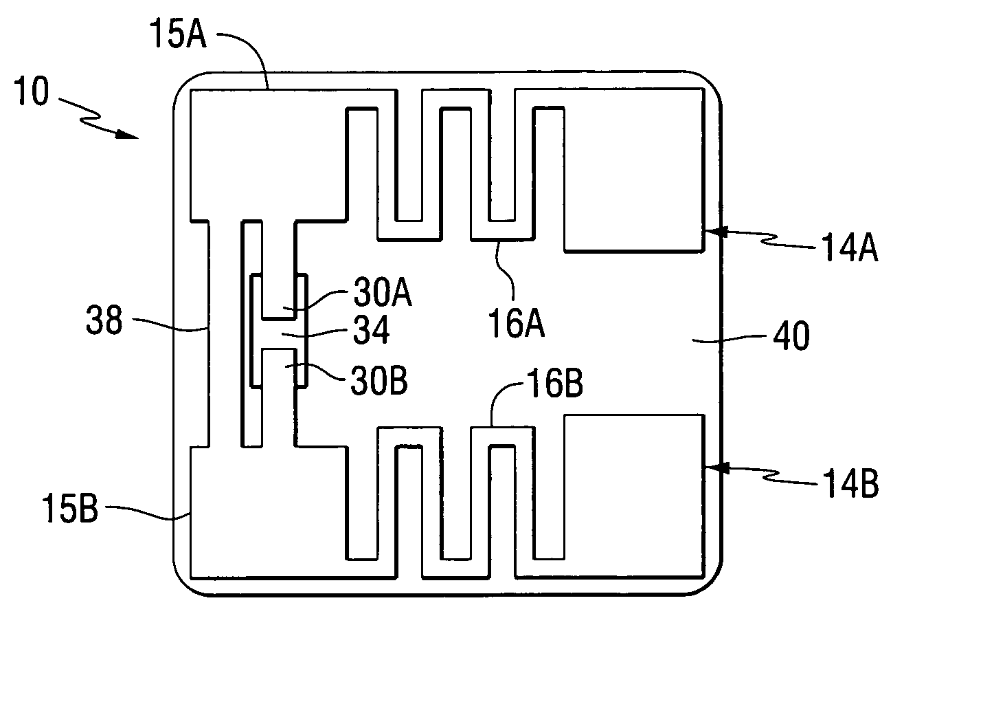
[0029]FIG. 1 illustrates a tag 10 comprising an antenna structure constructed according to the teachings of the present invention. The antenna comprises pads 14A, 14B, 15A and 15B with a meanderline 16A disposed between the pads 14A and 15A, and a meanderline 16B disposed between the pads 14B and 15B. Each of the meanderlines 16A and 16B compensate the desired antenna electrical length to achieve a resonant condition, i.e., where the desired electrical length is a mul...


PUM


Abstract

A radio frequency identification tag attached to an object and comprising an antenna and an integrated circuit for providing object information to a separate reader. The antenna further comprises a pair of meanderline transmission lines each terminated at a first end for conductive connection to the integrated circuit. A shorting bar connected between the pair of meanderline transmission lines at the first ends is operative to match an antenna impedance with an integrated circuit impedance.

Description

[0001] This patent application claims the benefit of the provisional patent application filed on May 29, 2003, which has been assigned application No. 60 / 474,128, and the provisional patent application filed on Sep. 17, 2003, which has been assigned Application No. 60 / 503,820.FIELD OF THE INVENTION [0002] The present invention relates generally to radio frequency identification tags and identification systems employing such tags, and more specifically to antennas for use in radio frequency identification tags. BACKGROUND OF THE INVENTION [0003] Radio frequency identification (RFID) is a rapidly growing segment of today's automatic identification and data collection industry. RFID technology is considered a complement and likely an eventual replacement for bar code technology as RFID technology overcomes certain recognized bar code limitations. In particular, a visual line of sight is not required between a reader and a tagged RFID object, as RFID technology is not optically based. I...

Claims


Application Information

Patent Timeline
IPC IPC(8): G06K19/077H01Q1/22H01Q1/36H01Q9/16H01Q9/28
CPCG06K19/0726G06K19/07749G06K19/07786H01Q9/285H01Q1/36H01Q9/16H01Q1/2225
Inventor JO, YOUNG-MINCAIMI, FRANK M.FARRAR, JOHN CHARLESTORNATTA, PAUL A. JR.
Owner SKYCROSS INC
Why Eureka
Try Eureka