
Manipulating an on-screen object using zones surrounding the object

a technology for manipulating objects and zones, applied in the direction of user-computer interaction, input/output, instruments, etc., can solve the problems of inconvenient use of user interface paradigms for manipulating objects of different types, user confusion, and cumbersome existing techniques for activating certain object manipulation operations,

Active Publication Date: 2005-02-03
RPX CORP
View PDF14 Cites 135 Cited by
  • Summary
  • Abstract
  • Description
  • Claims
  • Application Information

AI Technical Summary

Benefits of technology

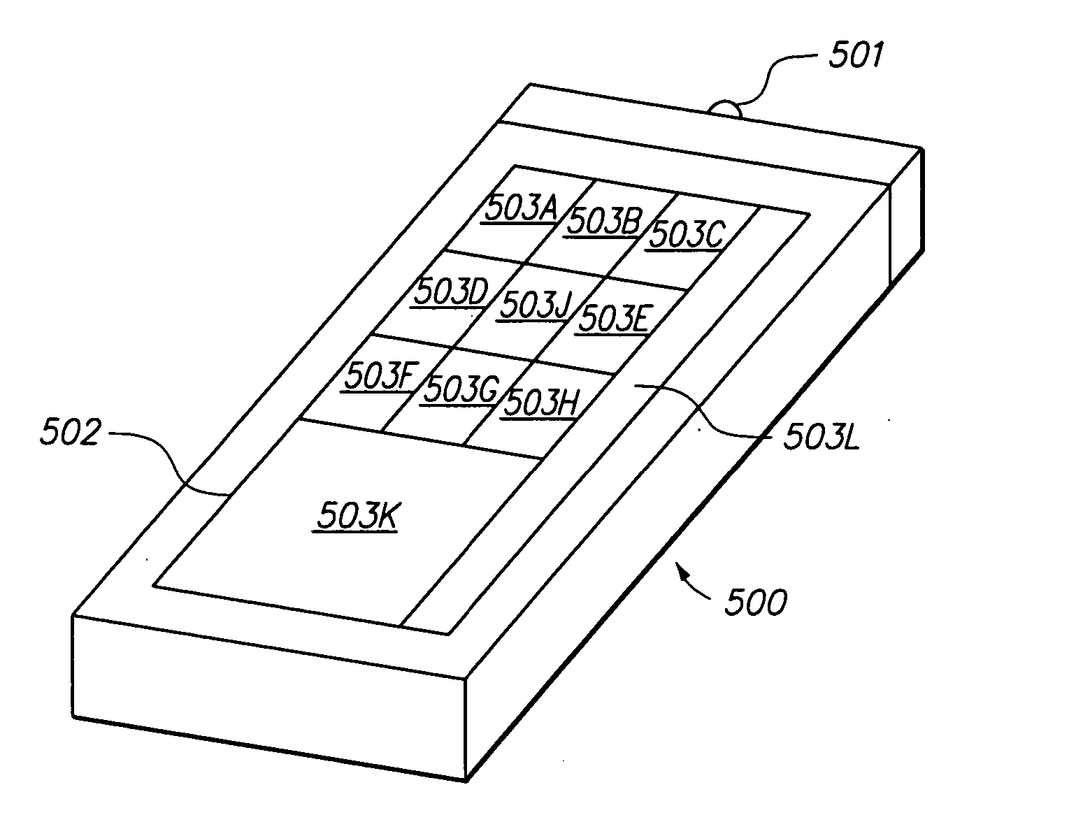
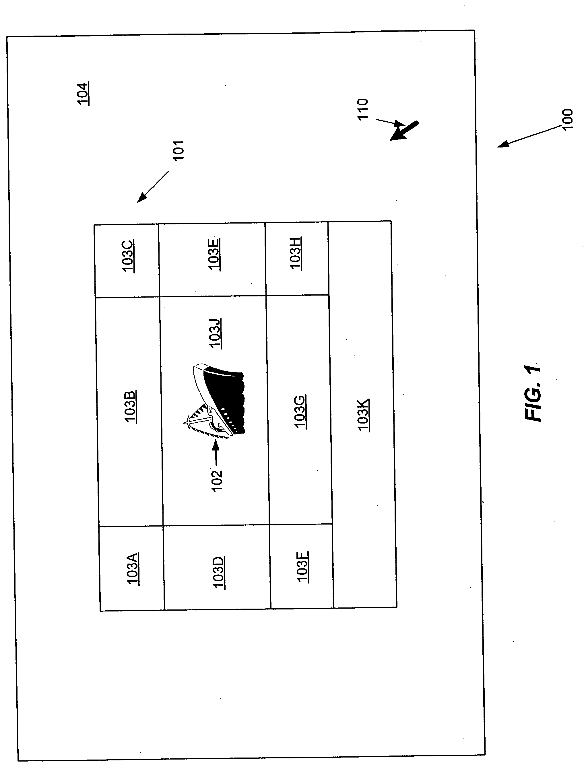
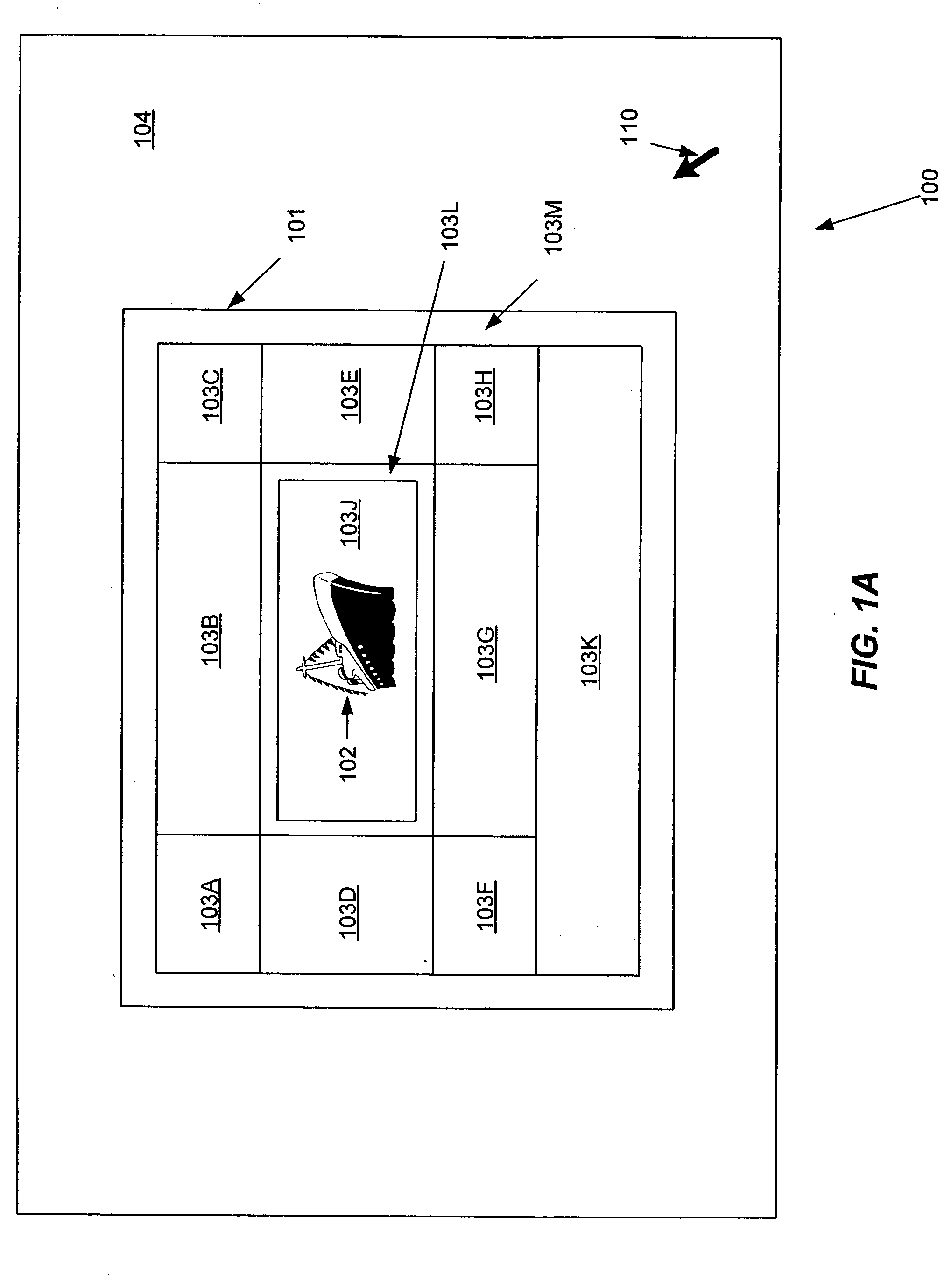
In one aspect of the present invention, each object is surrounded by a number of zones for performing various control operations on the object. The appearance of the zones can vary from one embodiment to another, but in general is kept consistent among various object types within a particular user interface. The zones surrounding an object are referred to collectively as a control region. Each zone of the control region is associated with a series of commands related to a particular type of editing or manipulation function. Displaying the control region around the object enables the user to immediately focus on and identify editing functions that can be performed on the object. Further, because of the proximity of the control region about the object, the user does not need to move the cursor to a distinct menu, tool palette, or other user interface element, and as such, the user can select and execute the desired command more quickly and efficiently.
The invention thus provides an easy-to-use, understandable user interface paradigm wherein the control region for each object surrounds the object itself, provides access to all relevant editing operations with respect to the object, and provides multiple input modes that operate consistently, and wherein interactions with zones are consistent from one object type to another.

Problems solved by technology

One problem with most existing techniques is that there is no consistent user interface paradigm for manipulating objects of different types.
Often users become disoriented and confused when attempting to control certain types of objects, particularly when the user interface elements for the object being controlled differ from those to which the user has become accustomed.
Furthermore, existing techniques for activating certain object manipulation operations can be cumbersome, difficult to learn, or counterintuitive.
In addition, many such techniques do not translate well from one input mechanism to another (such as pen-based, mouse, voice, and keyboard input mechanisms).

Method used


Image

  • Manipulating an on-screen object using zones surrounding the object
  • Manipulating an on-screen object using zones surrounding the object
  • Manipulating an on-screen object using zones surrounding the object

Examples


example

Tables and Cells

The present invention provides a consistent interface for manipulating the characteristics of table objects and cell objects. Sizes, such as row heights, column widths, and overall table sizes, can be specified in absolute terms or as a percentage of a containing object. For example, a cell width can be configured to be 25% of the width of the containing table; if the table width is increased, the cell width increases proportionately. The user interface allows for selection and operation on individual cells, rows, columns, or the entire table. In one embodiment, for example, clicking on a corner of the table selects the entire table; clicking on the left or right edge selects the table row at the clicked location; clicking on the top or bottom edge selects the table column at the clicked location; and clicking on a cell selects the individual cell. In one embodiment, the control region is presented for the selected cell, column, row, or table, so that the user can ...


PUM


Abstract

A user interface for manipulating objects of various types in a consistent manner. Each on-screen object is surrounded by a control region including a number of zones for performing various control operations on the object. Multiple input modes are available for interacting with the zones, allowing object manipulation commands to be initiated in several different ways, such as via stroke input, pressing a mouse button, double-clicking, menu selection, voice input, and the like. The user interface is operable using any of several different types of input devices.

Description

BACKGROUND OF THE INVENTION 1. Field of the Invention The present invention relates generally to user interfaces for managing on-screen objects, and more particularly to a user interface that provides a consistent set of object management zones surrounding an on-screen object. 2. Description of the Background Art Existing user interfaces provide many different techniques for moving, altering, controlling, and otherwise manipulating on-screen objects such as windows, images, text blocks, video, and the like. For example, the Windows XP operating system, available from Microsoft Corporation of Redmond, Wash., provides user interface mechanisms for manipulating various types of on-screen objects. Examples of such user interface mechanisms include: application menus (e.g., click on an object to select it, and select an operation from an application menu); on-screen buttons (e.g., click on an object to select it, and click a button to perform an operation on the object); context-s...

Claims


Application Information

Patent Timeline
IPC IPC(8): G06FG06F3/023G06F3/038G09G5/00
CPCG06F3/0231G06F3/038G06F3/0481G06F3/0482G06F2203/04803G06F3/04886G06F2203/0381G06F2203/0384G06F3/04883
Inventor KUPKA, SIG G.
Owner RPX CORP
Learn More