Motion type decision apparatus and method thereof

a motion type and decision apparatus technology, applied in the field of motion type decision apparatus and motion type decision apparatus, can solve the problems of affecting the quality of subsequent image, and inaccurate estimation of motion vectors for respective blocks

Inactive Publication Date: 2005-02-03
SAMSUNG ELECTRONICS CO LTD
View PDF10 Cites 30 Cited by
  • Summary
  • Abstract
  • Description
  • Claims
  • Application Information

AI Technical Summary

Benefits of technology

[0018] According to one aspect of the present invention, a motion type decision method comprises a first decision step of determining the presence of motion in a current block for compensation, by extracting first and second high frequency signals from a first block and a second block of a previous and a current frame/fields corresponding to a zero motion vector of the current block to set a first threshold, and comparing a first motion estimation error value between the first and the second blocks with the first threshold; a second decision step of determining the presence of motion in the current block, by extracting third and fourth high frequency signals from a third block and a fourth block of the previous and the current frame/fields corresponding to a motion vector, which is estimated for the compensation of the current block, to set a second threshold, and comparing a second motion estimation error value between the third and the fourth blocks with the second threshold; and a motion type decision step of determining a motion type of the current block by comparing the determination on the presence of motion by the first and the second decision steps.
[0019] T

Problems solved by technology

However, in the conventional motion estimation, motion vectors estimated for the respective blocks were often inaccurate, and when this happened, there occurred a block artifact in an interpolated frame/field image as shown in FIG. 1 as the motion compensa

Method used


Image

  • Motion type decision apparatus and method thereof
  • Motion type decision apparatus and method thereof
  • Motion type decision apparatus and method thereof

Examples


Embodiment Construction

[0030] Hereinafter, the present invention will be described in detail with reference to the accompanying drawings.

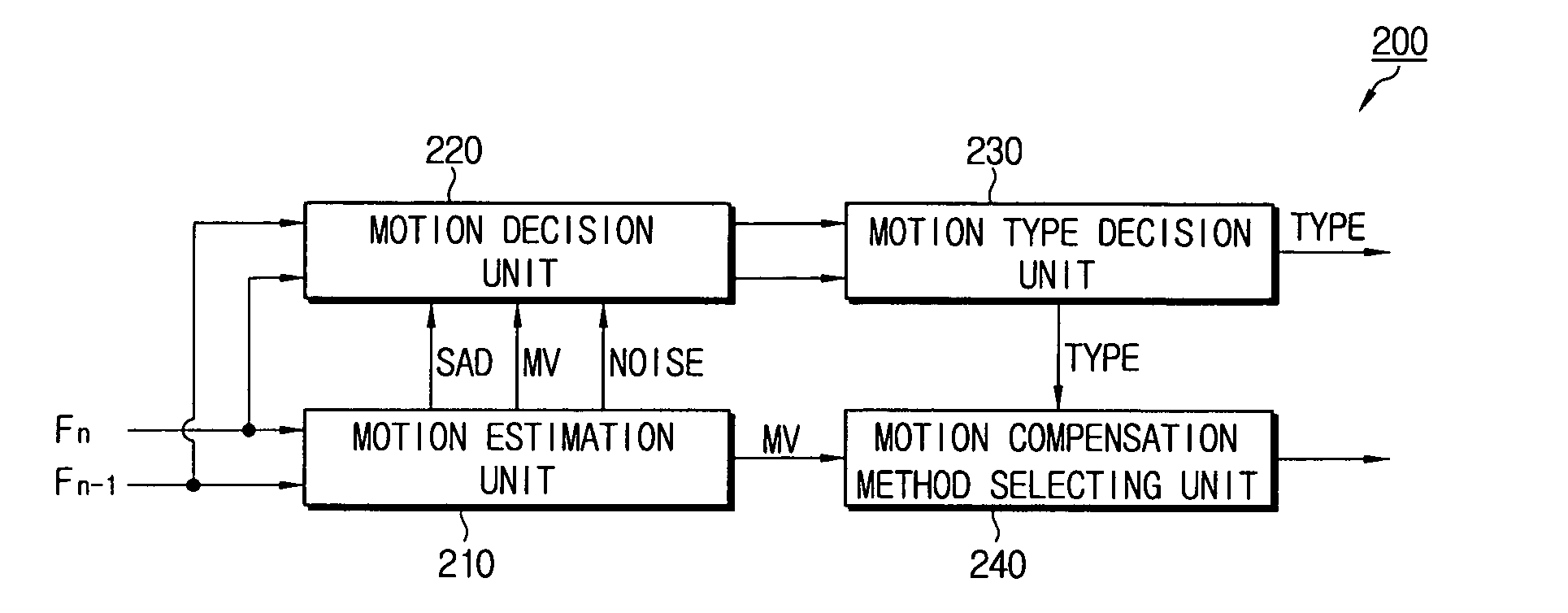
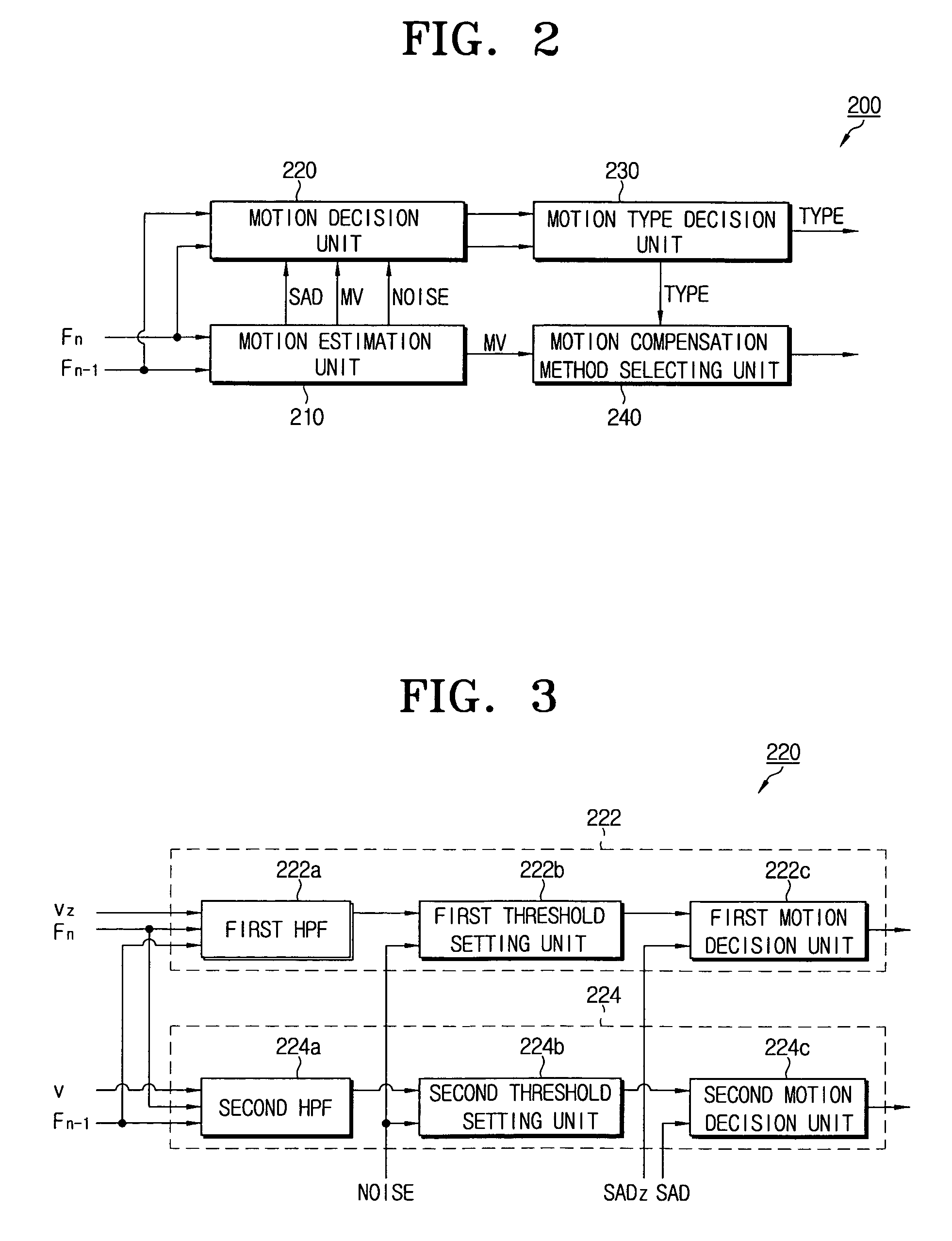
[0031]FIG. 2 is a block diagram schematically illustrating a motion-type adaptive motion compensation selecting apparatus according to a first exemplary embodiment of the present invention, and FIG. 3 is a block diagram illustrating in detail the motion decision unit of FIG. 2.

[0032] Referring to FIG. 2, a motion-type adaptive motion compensation selecting apparatus 200 according to the present invention includes a motion estimation unit 210, a motion decision unit 220, a motion type decision unit 230 and a motion compensation method selecting unit 240. The motion decision unit 220 and the motion type decision unit 230 of FIG. 2 are applied as a motion type decision apparatus according to the present invention.

[0033] The motion estimation unit 210 divides a currently-input frame / field (hereinafter briefly called ‘current frame Fn’) into blocks of a predetermined size,...


PUM


Abstract

A motion type decision apparatus and method thereof are provided. A first decision unit determines the presence of motion in a current block for compensation, by extracting first and second high frequency signals from first and second blocks of a previous and a current frame/fields corresponding to a zero motion vector of the current block to set a first threshold, and comparing a first motion estimation error value between the first and the second blocks with the first threshold. A second decision unit determines the presence of motion in the current block, by extracting third and fourth high frequency signals from third and fourth blocks, setting a second threshold, and comparing a second motion estimation error value with the second threshold. A motion type decision unit determines a motion type of the current block by comparing the motion determinations of the first and the second decision units.

Description

CROSS-REFERENCE TO RELATED APPLICATIONS [0001] This application claims the benefit of Korean Patent Application No. 2003-53230 filed Jul. 31, 2003, in the Korean Intellectual Property Office, the disclosure of which is incorporated herein by reference. BACKGROUND [0002] 1. Field of the Invention [0003] The present invention relates to an apparatus and a method for motion type decision, and more particularly, to a motion type decision apparatus and method thereof, which decides the motion type of a current block for compensation, by considering a zero motion vector of the current block and motion vectors which are estimated by block matching. [0004] 2. Description of the Related Art [0005] In a general image processing operation such as a frame rate up-conversion (FRC) or an interlaced to progressive conversion (IPC), motion estimation among image frames is essentially required. The motion estimation refers to a process which estimates motion vectors for motion compensation, and is u...

Claims


Application Information

Patent Timeline
IPC IPC(8): G06T7/20H04N7/32H04N5/14H04N7/26H04N7/36
CPCG06T7/2013G06T2207/10016H04N19/51H04N19/503H04N5/145G06T7/223
Inventor SOHN, YOUNG-WOOKLEE, SUNG-HEE
Owner SAMSUNG ELECTRONICS CO LTD
Why Eureka
Try Eureka