Method of forming a decorative motif on a component of lighting or indicating apparatus for a motor vehicle

Inactive Publication Date: 2005-02-03
VALEO VISION SA
View PDF5 Cites 6 Cited by
  • Summary
  • Abstract
  • Description
  • Claims
  • Application Information

AI Technical Summary

Benefits of technology

[0007] The present invention aims to provide a method for making a decorative motif on a component of a lighting or indicating apparatus for a motor vehicle, which enables accurate motifs to be forme

Problems solved by technology

Such motifs or patterns are obtained, in a first method, by marking the mould in which the components are made, but this leads to lack of flexibility and a tendency to induce wear in the mould.
The mould can easily become worn, or be contaminated by impurities.
This method gives rise to problems of fastness of the ink over the life of the co

Method used


Image

  • Method of forming a decorative motif on a component of lighting or indicating apparatus for a motor vehicle
  • Method of forming a decorative motif on a component of lighting or indicating apparatus for a motor vehicle

Examples


Embodiment Construction

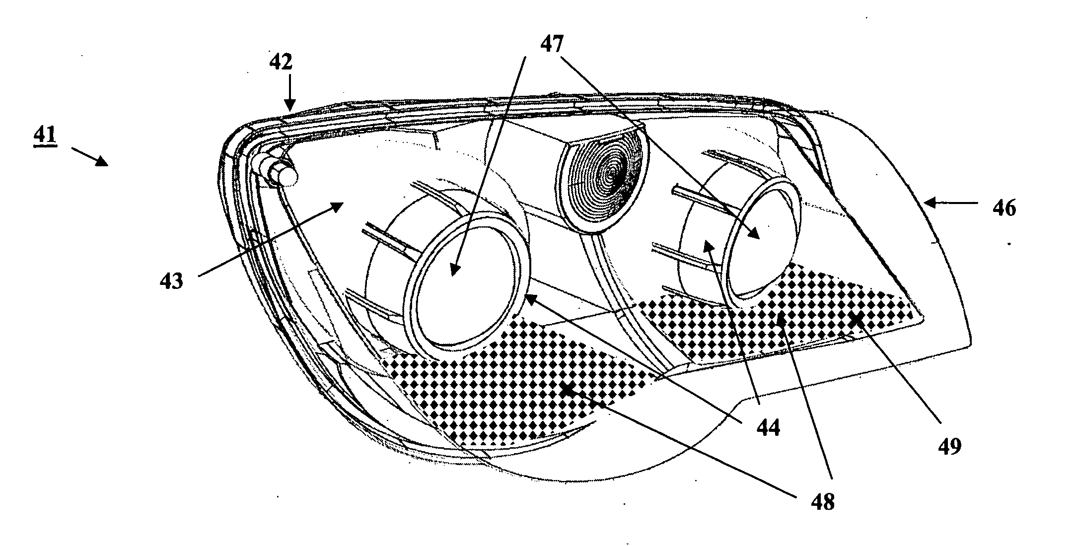
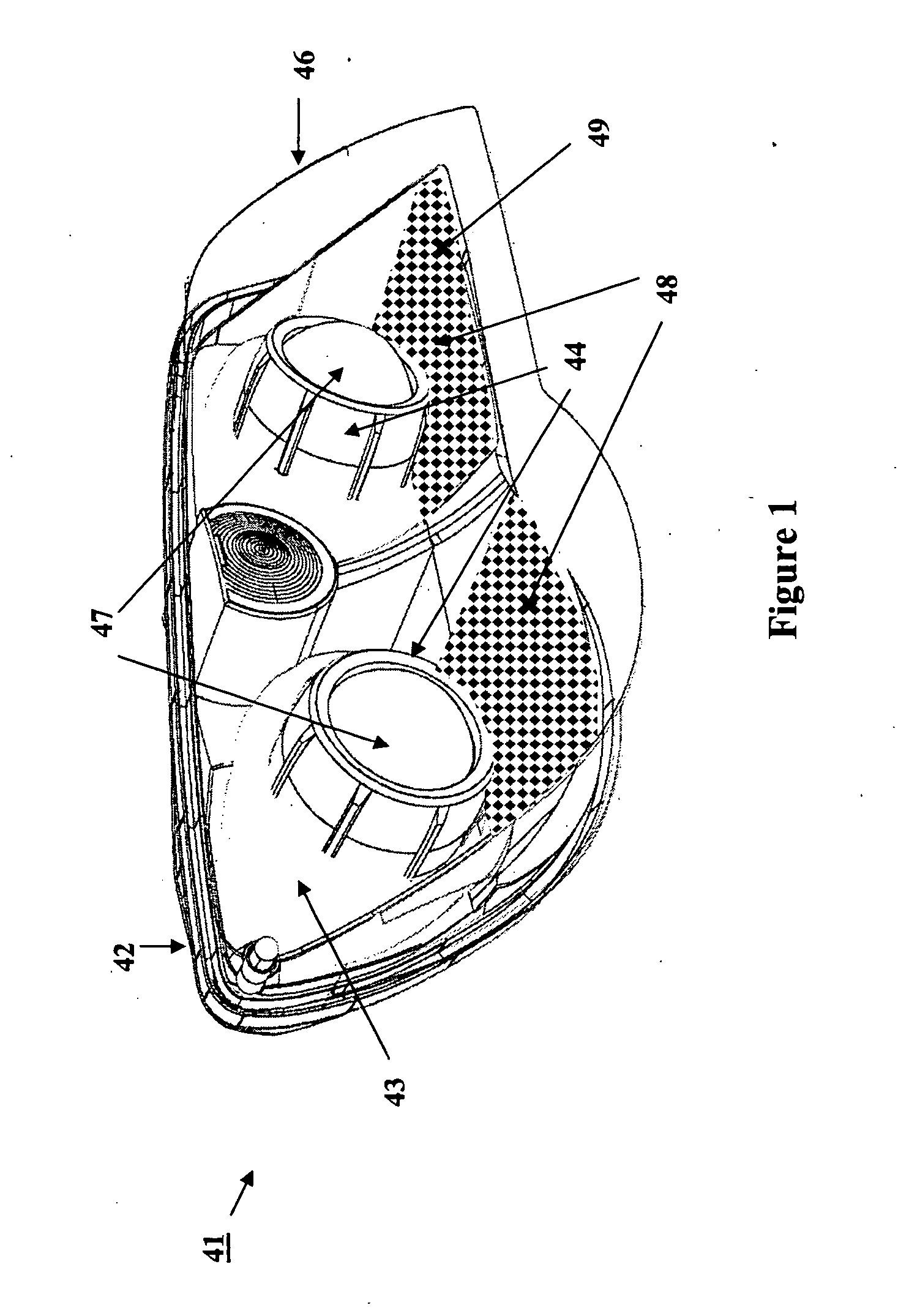
[0028]FIG. 1 shows diagrammatically a headlight 41 which includes a mask having decorative motifs obtained by the method of the invention.

[0029] In particular, the headlight 41 comprises: [0030] a housing 42, [0031] a protective front glass 46, [0032] elliptical headlight lenses 47, and [0033] a mask 43.

[0034] The three elements consisting of the housing 42, protective glass 46 and mask 43 are injection moulded in thermoplastic material.

[0035] The mask 43 has two openings 44 for the elliptical headlight lenses 47.

[0036] The mask 43 includes two surfaces 48, and each of these two surfaces 48 comprises a plurality of black lozenges 49.

[0037] The mask 43 is injection moulded in black-body coloured thermoplastic material.

[0038] The mask 43 is then metallised with an aluminium layer completely covering it.

[0039] Selective removal of the aluminium layer is then carried out in such a way as to reveal the black lozenges 49.

[0040] This method accordingly enables a mask to be made at ...


PUM

PropertyMeasurementUnit
Thermoplasticityaaaaaaaaaa

Abstract

The present invention relates to a method of making a decorative motif on a component of a lighting or indicating apparatus for a motor vehicle. The method is adapted more particularly to making the mask for a headlight or indicator light. The method includes a step of forming the said component in a predetermined material, and a step of exposing at least one surface of the said component to laser radiation.

Description

FIELD OF THE INVENTION [0001] The present invention relates to a method of forming a decorative motif or pattern on a component of a lighting or indicating apparatus for a motor vehicle. This method is more particularly adapted to forming motifs on masks or bodies for headlights or indicator lights. BACKGROUND OF THE INVENTION [0002] Motor manufacturers very often require there to be particular motifs or patterns on lighting or indicating devices. These motifs, which are precise and indelible, and are formed on certain components such as the mask of the headlight or the body of the indicating light, are most usually provided for aesthetic purposes only. [0003] Such motifs or patterns are obtained, in a first method, by marking the mould in which the components are made, but this leads to lack of flexibility and a tendency to induce wear in the mould. The mould can easily become worn, or be contaminated by impurities. [0004] A second method consists in deposition of inks (screen proc...

Claims


Application Information

Patent Timeline
IPC IPC(8): B41J2/44B29C59/16B41M5/24B44C1/22B60Q1/00F21S8/10F21V3/04F21V5/00F21V9/08F21W107/10
CPCB41M5/24B44C1/228B60Q1/0041F21S48/1233Y10T428/24917F21S48/2218F21S48/25F21V3/04F21S48/2212F21S41/28F21S43/255F21S43/26F21S43/50
Inventor GIROUD, THOMAS
Owner VALEO VISION SA
Why Eureka
Try Eureka