Spring clip safety IV catheter

a safety iv catheter and spring clip technology, applied in the field of safety iv catheters, can solve the problems of limited usefulness and full acceptance of the patient, the force required to engage the needle slot within the guard flange is relatively large, and the health care worker is vulnerable to the transmission of various dangerous blood-borne pathogens

Active Publication Date: 2005-02-03
B BRAUN MELSUNGEN AG
View PDF52 Cites 160 Cited by
  • Summary
  • Abstract
  • Description
  • Claims
  • Application Information

AI Technical Summary

Benefits of technology

[0010] It is accordingly an object of the present invention to provide a safety IV catheter which reliably and automatically prevents accidental, inadvertent contact with the needle tip after use.

Problems solved by technology

The problem is that, immediately after the withdrawal of the needle from the patient's vein, the healthcare worker, who is at this time involved in at least two urgent procedures, must place the exposed needle tip at a nearby location and address the tasks required to accomplish the needle withdrawal.
It is at this juncture that the exposed needle tip creates a danger of an accidental needle stick occurring, which, under the circumstances, leaves the healthcare worker vulnerable to the transmission of various dangerous blood-borne pathogens, including AIDS and hepatitis.
The prior art safety catheters all exhibit one or more drawbacks that have thus far limited their usefulness and full acceptance by healthcare workers.
For example, in the safety catheter disclosed in the Lemieux patent, the force required to engage the needle slot within the guard flange is relatively great and would interfere with the removal of the needle.
As a result, the safety catheter disclosed in the Lemieux patent would not consistently function in a reliable manner.
Similarly, the user of the safety catheter disclosed in the Dombrowski patent would have to exert a considerable force to remove the protective cap from the catheter hub when the cap engages a needle.
The safety catheter disclosed in the Dombrowski patent would also be relatively expensive to fabricate because of its inclusion of a flexible flange and a tether.
The McLees device also requires the assembly of two separate components and is thus relatively costly to manufacture.

Method used


Image

  • Spring clip safety IV catheter
  • Spring clip safety IV catheter
  • Spring clip safety IV catheter

Examples


Embodiment Construction

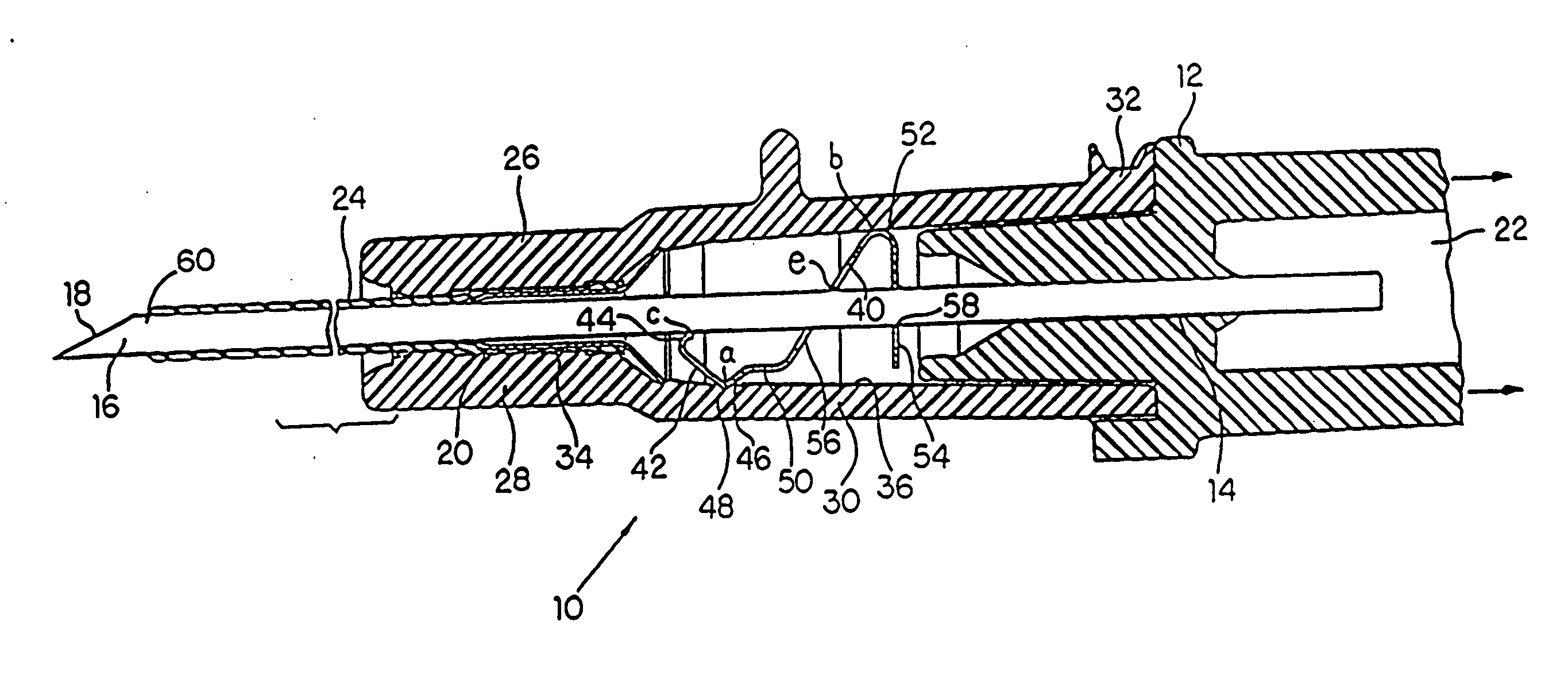
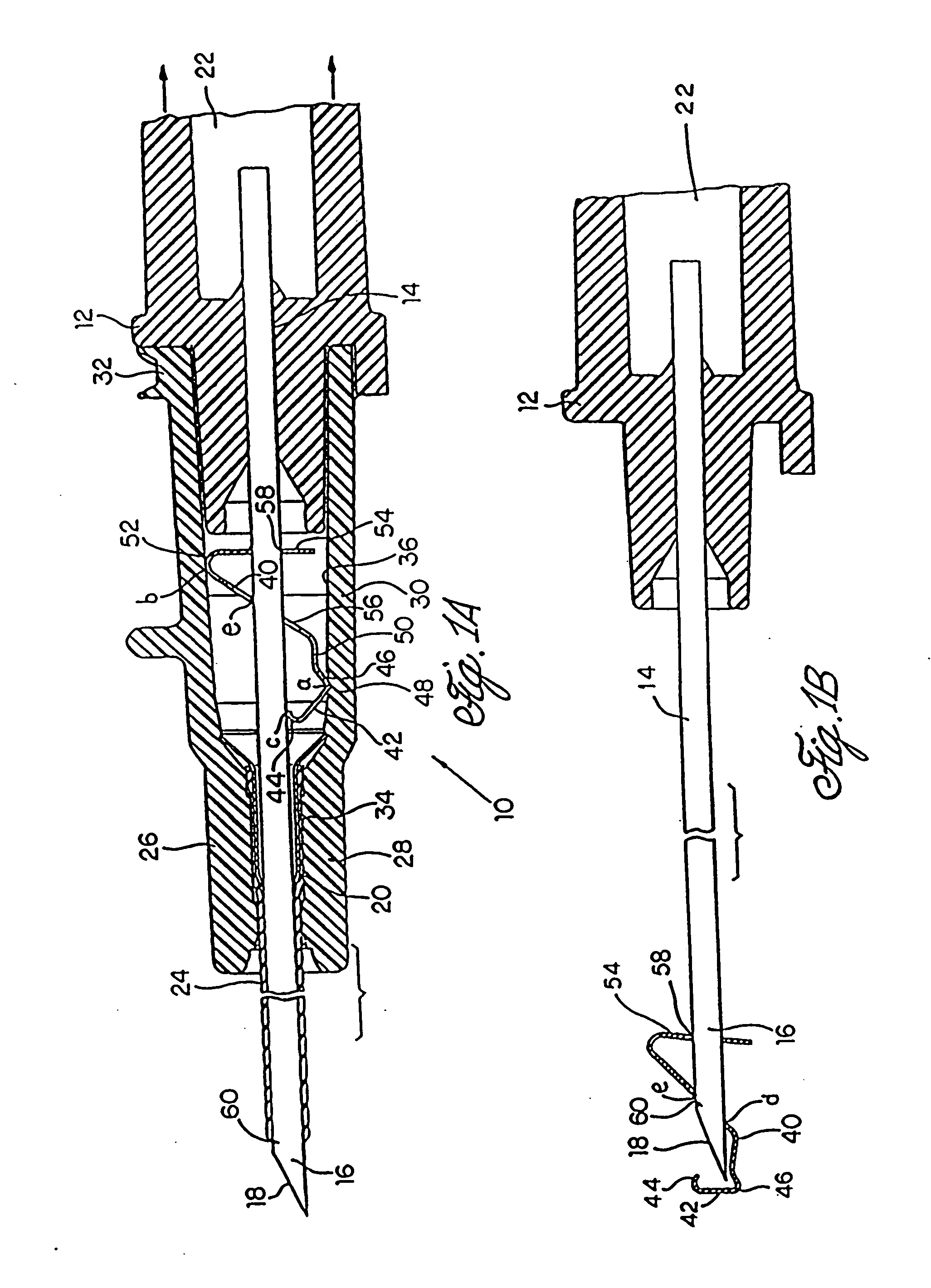
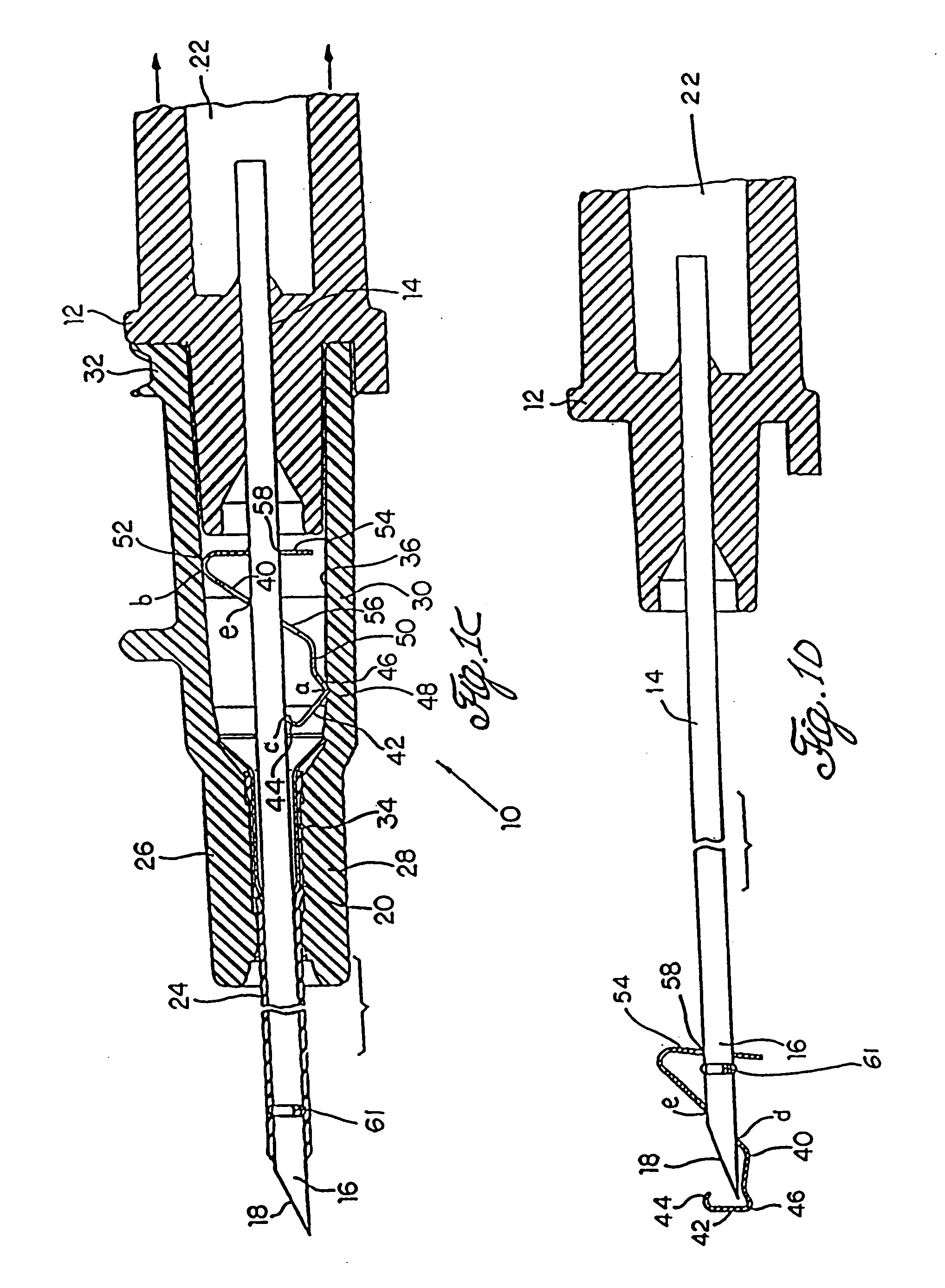
[0045] The safety IV catheter of the invention, generally designated 10 in the embodiment illustrated in FIGS. 1A and 1B, includes a needle hub 12 that includes an axial opening 14 which securely receives the proximal end of a needle 16 having a sharpened tip 18. The needle hub 12, as is conventional, is hollow and includes a flash chamber 22. As is also conventional, the needle 16 is received within a hollow tubular catheter 24, the proximal end of which is concentrically affixed within the distal end of a catheter hub 26 having a distal section 28 and a contiguous, larger diameter proximal section 30.

[0046] The catheter hub 26 terminates at its proximal end in a Luer fitting 32 adapted to receive a tubing set which, in a known manner, administers intravenous fluid into the patient. The catheter 24 is secured within an axial passageway 34 in the distal hub section 28 by means of a sleeve 20 received within the passageway 34, which engages the proximal end of the catheter. Passagew...


PUM


Abstract

A safety IV catheter includes a unitary, resilient needle guard received in a catheter hub. The needle guard includes a proximal arm or wall that includes an opening through which a needle passes for axial movement. When the needle is retracted from the catheter, it releases the force that had previously prevented movement of the needle guard within the catheter hub. This in turn causes the needle guard to snap into a position in which it is clamped onto the needle shaft and in which its distal wall blocks access to the needle tip. In this condition, the spring needle guard and needle can be removed from the catheter hub. A slot or crimp may be formed in the needle shaft that engages with the needle guard after the protected needle and needle guard are removed from the catheter hub, thereby to prevent removal of the protected needle from the needle guard.

Description

CROSS-REFERENCE TO RELATED APPLICATIONS [0001] This is a continuation-in-part of pending application Ser. No. 10 / 445,166, filed May 23, 2003, which is a continuation of application Ser. No. 09 / 638,641, filed Aug. 14, 2000, now U.S. Pat. No. 6,616,630, which is a continuation-in-part of application Ser. No. 09 / 183,697, filed Oct. 30, 1998, now U.S. Pat. No. 6,287,278, which is a continuation-in-part of application Ser. No. 09 / 097,170, filed Jun. 12, 1998, now U.S. Pat. No. 6,117,108, which is a continuation-in-part of application Ser. No. 08 / 915,148, filed Aug. 20, 1997, now abandoned, the contents of which are expressly incorporated herein by reference.FIELD OF THE INVENTION [0002] This invention relates generally to intravenous (IV) catheters, and, in particular, to a safety IV catheter in which the needle tip is automatically covered after needle withdrawal to prevent the healthcare worker from making accidental contact with the needle tip. BACKGROUND OF THE INVENTION [0003] IV ca...

Claims


Application Information

Patent Timeline
Patent Type & Authority Applications(United States)
IPC IPC(8): A61M5/158A61M5/32A61M25/06
CPCA61M5/158A61M5/3273A61M5/3275A61M2005/325A61M25/0618A61M25/0625A61M2005/3247A61M25/0606
Inventor WOEHR, KEVINORTH, MANFREDWYNKOOP, MARK
Owner B BRAUN MELSUNGEN AG
Why Eureka
Try Eureka