
Method and apparatus for intervertebral implant anchorage

Inactive Publication Date: 2005-02-03
INFINITY ORTHOPAEDICS
View PDF99 Cites 212 Cited by
  • Summary
  • Abstract
  • Description
  • Claims
  • Application Information

AI Technical Summary

Benefits of technology

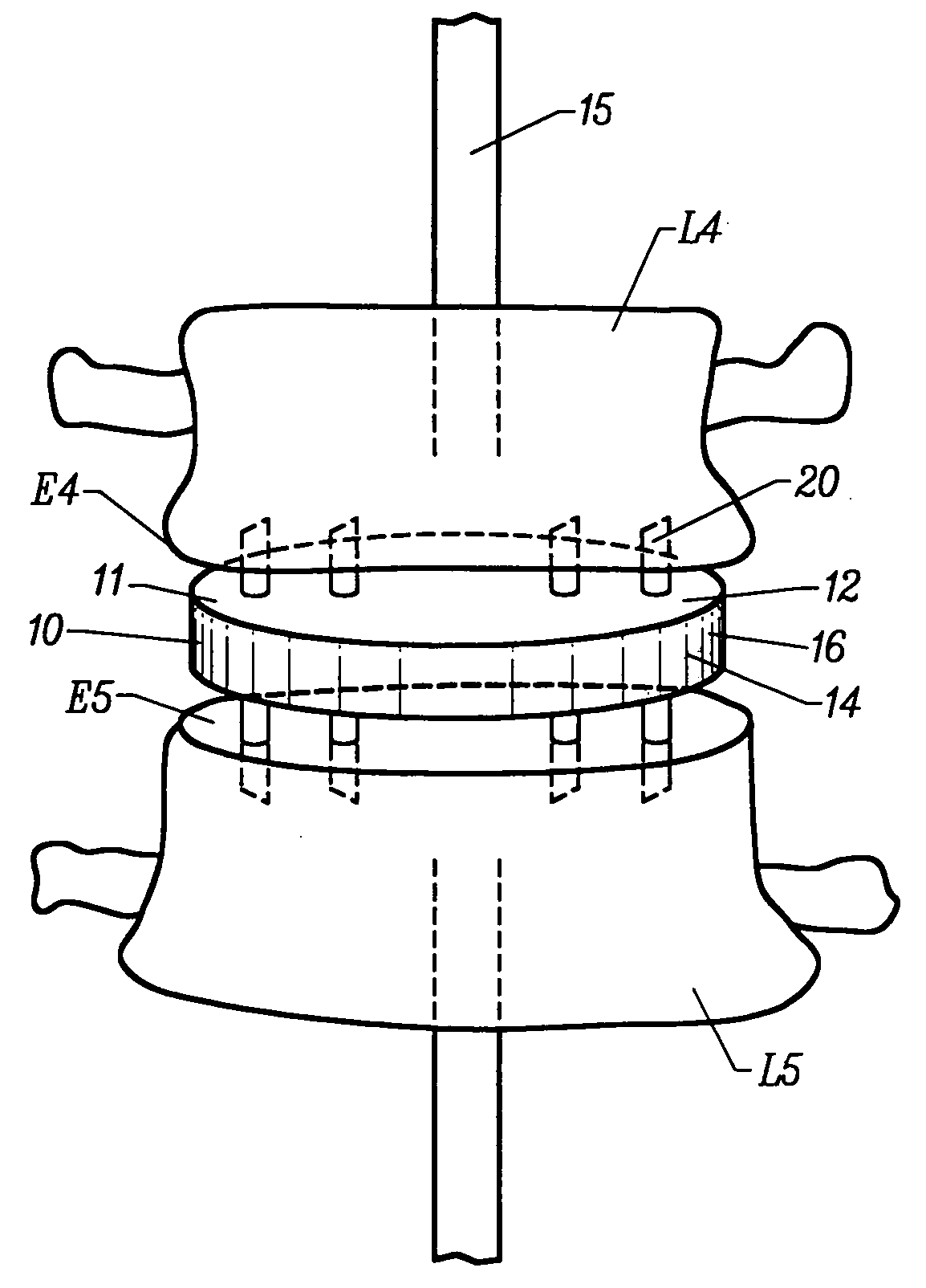
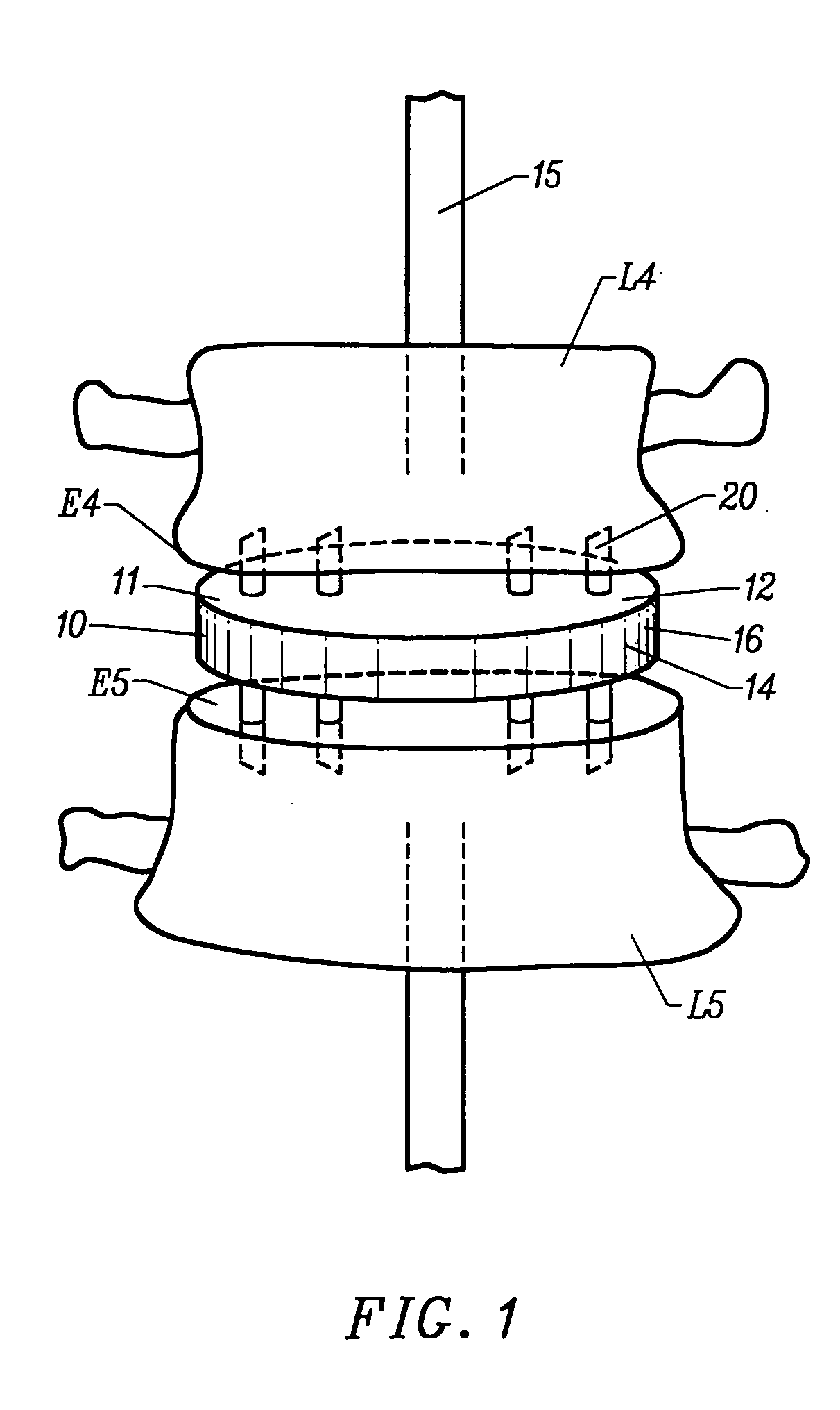
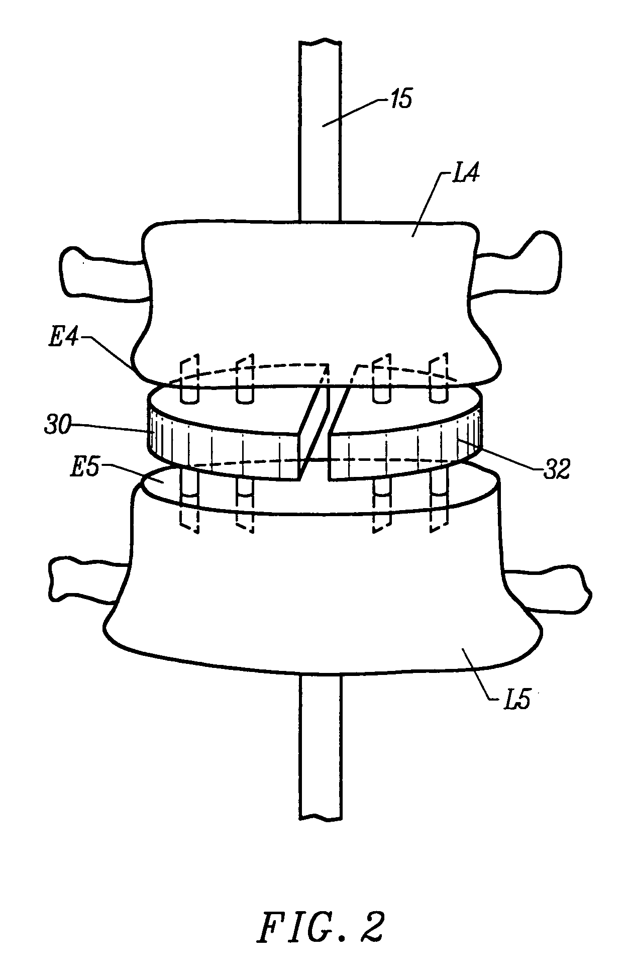
[0008] An anchoring plate is provided for anchoring an intradiscal device to an end plate of a vertebra. The anchoring plate includes a plate member sized to be positioned within an intradiscal section between adjacent vertebrae and a plurality of anchoring elements extending from a surface of the plate member, each anchoring element including a distal portion capable of being introduced into the vertebra through the vertebral end plate. In one embodiment, at least one of the anchoring elements includes a lumen. The lumen allows ingrowth of the bone graft material through the lumen to the end-plate of the vertebra. The lumen preferably has a diameter between about 0.5 mm-9 mm.
[0021] The anchoring elements can have a plurality of shapes including cone, cylinder, triangle, square, rectangle and other irregular shapes so long as the anchoring elements are capable of being introduced into an end plate of a vertebra. The anchoring elements can extend from the plate member substantially vertically, angularly or curved. The anchoring elements are preferably shaped so as to minimize the risk of splintering the vertebra by introducing the anchoring elements into the vertebra.

Problems solved by technology

Back pain remains a major public health problem, especially among aged people.
Persistent and severe back pain often causes debility and disability, and such a pain is closely associated with intervertebral disc abnormalities of the spine.
Because of exertion, injury, illness, accident or abuse, one or more of the vertebrae and / or one or more discs may become damaged and malfunctioning.
However, it is often necessary to remove at least a portion of the damaged and / or malfunctioning back component.
One of the disadvantages of these interlocked implants is that, the implants may not be stable enough to withstand rotation and may lead to implant loosening and failure of the prosthesis.
A disadvantage of this device is a tendency for the anchoring screws to become dislodged.

Method used


Image

  • Method and apparatus for intervertebral implant anchorage
  • Method and apparatus for intervertebral implant anchorage
  • Method and apparatus for intervertebral implant anchorage

Examples


Embodiment Construction

[0053] The present invention relates to devices which may be anchored to vertebrae of the spine by introducing anchoring elements through an end plate of the vertebrae. In particular, an anchoring plate, which comprises a plurality of anchoring elements such as spikes or prongs extending from the plate, is provided for anchoring an intradiscal device to an end plate of a vertebra. By securing the anchor plate to an end plate of the vertebra, a surgeon operating on a patient's spine can attach a variety of intradiscal components to the anchor plates. The secured anchorage and support provided by the apparatus of the present invention prevents loosening of the apparatus and enhances the fusion of the adjacent vertebrae.

[0054] A variety of intradiscal components can be incorporated into the apparatus of the present invention. In one embodiment, the intradiscal component includes a cage within which the anchor plate is contained. Bone graft material can be filled into the cage which is...


PUM


Abstract

Methods and devices are provided for intervertebral implant anchorage. An implantable device for insertion into an intradiscal section between adjacent vertebrae is provided. The implantable device includes at least one anchor plate which comprises a plate member sized to be positioned within an intradiscal section between adjacent vertebrae and a plurality of anchoring elements extending from a surface of the plate member, each anchoring element including a distal—portion capable of being introduced into the vertebra through the vertebral end plate; and an intradiscal component coupled to the anchor plate.

Description

FIELD OF THE INVENTION [0001] The present invention relates to methods and devices for treating intervertebral disc diseases and more particularly to intervertebral prostheses for positioning in an intervertebral space to treat intervertebral disorders. BACKGROUND OF THE INVENTION [0002] Back pain remains a major public health problem, especially among aged people. Persistent and severe back pain often causes debility and disability, and such a pain is closely associated with intervertebral disc abnormalities of the spine. [0003] The human spine is a flexible structure comprised of thirty-three vertebrae. Intervertebral discs separate and cushion adjacent vertebrae, and act as shock absorbers and allow bending between the vertebrae. An intervertebral disc comprises two major components: the nucleus pulposus and the annulus fibrosis. The nucleus pulposus is centrally located in the disc and occupies 25-40% of the disc's total cross-sectional area. The annulus fibrosis surrounds the n...

Claims


Application Information

Patent Timeline
IPC IPC(8): A61B17/02A61F2/00A61F2/28A61F2/30A61F2/44A61F2/46
CPCA61B2017/0256Y10S606/912A61F2/30767A61F2/30965A61F2/44A61F2/442A61F2/4425A61F2/4455A61F2/4611A61F2002/2835A61F2002/30113A61F2002/30125A61F2002/30153A61F2002/30154A61F2002/30158A61F2002/30187A61F2002/30225A61F2002/30235A61F2002/3028A61F2002/3051A61F2002/30579A61F2002/30594A61F2002/30604A61F2002/30772A61F2002/3078A61F2002/30785A61F2002/30787A61F2002/30789A61F2002/30841A61F2002/30892A61F2002/30971A61F2002/30975A61F2002/4475A61F2002/448A61F2002/4635A61F2220/0025A61F2230/0006A61F2230/0008A61F2230/0019A61F2230/0021A61F2230/0026A61F2230/0034A61F2230/0063A61F2230/0069A61F2240/001A61F2310/00017A61F2310/00023A61F2310/00029A61F2310/00203A61F2310/00239A61F2310/00796A61F2310/00976Y10S606/907Y10S606/91Y10S606/909A61F2/30724A61F2002/30507A61F2002/30777A61F2002/30593
Inventor WILLIAMS, LYTTON A.WATKINS, ROBERT G.
Owner INFINITY ORTHOPAEDICS
Learn More