Upright vacuum cleaner with cyclonic air flow
- Summary
- Abstract
- Description
- Claims
- Application Information
AI Technical Summary
Benefits of technology
Problems solved by technology
Method used
Image
Examples
Embodiment Construction
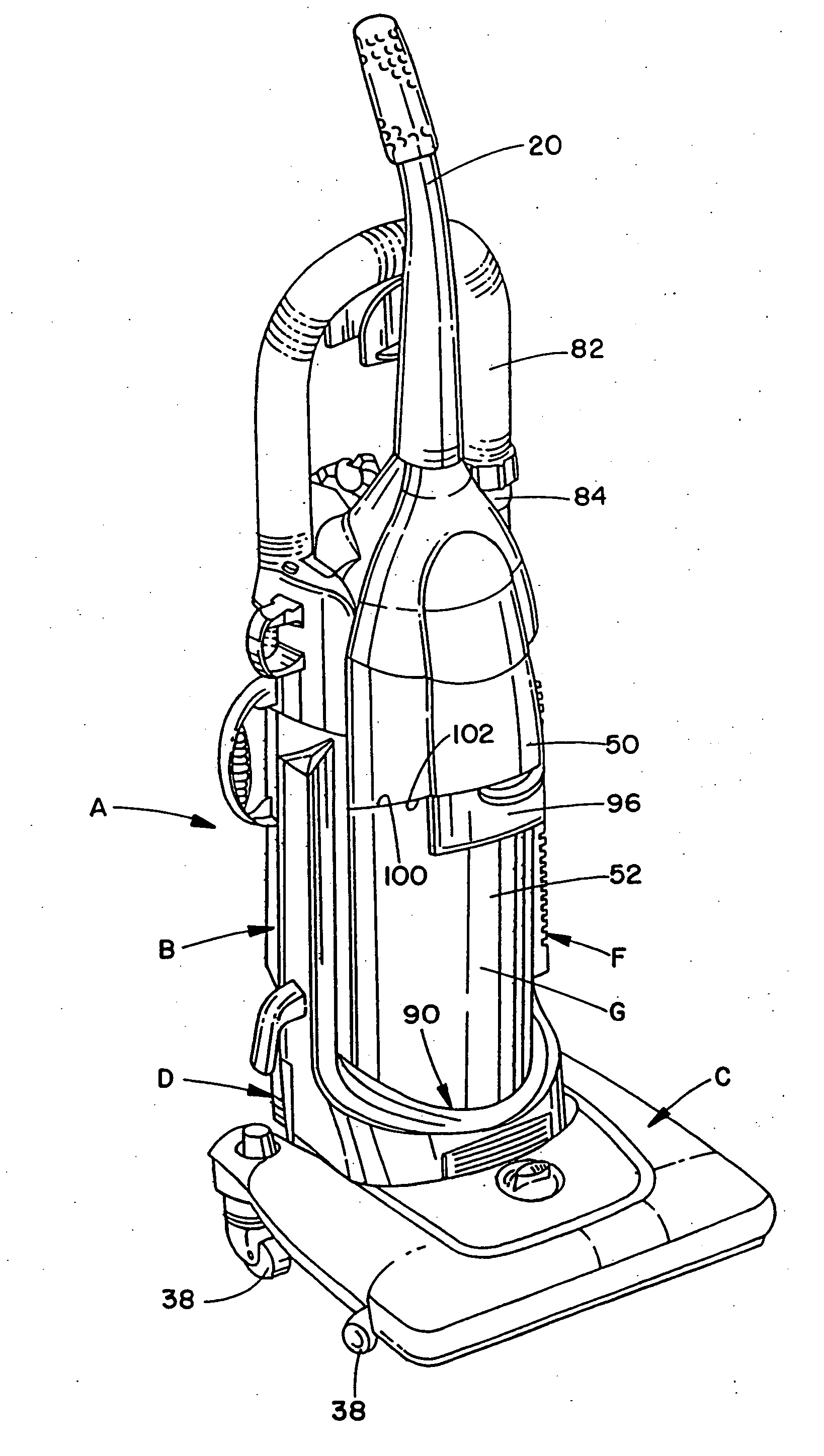
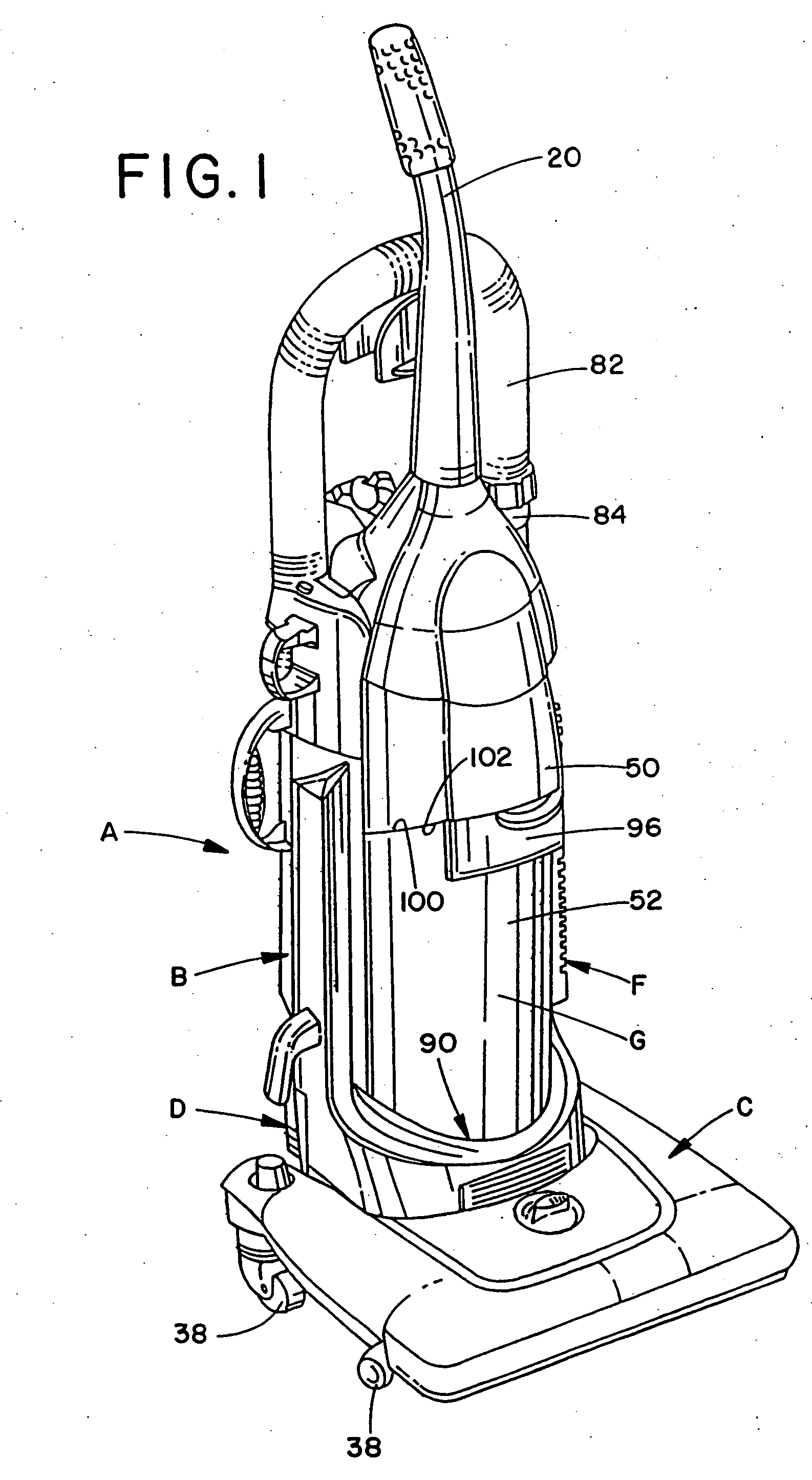
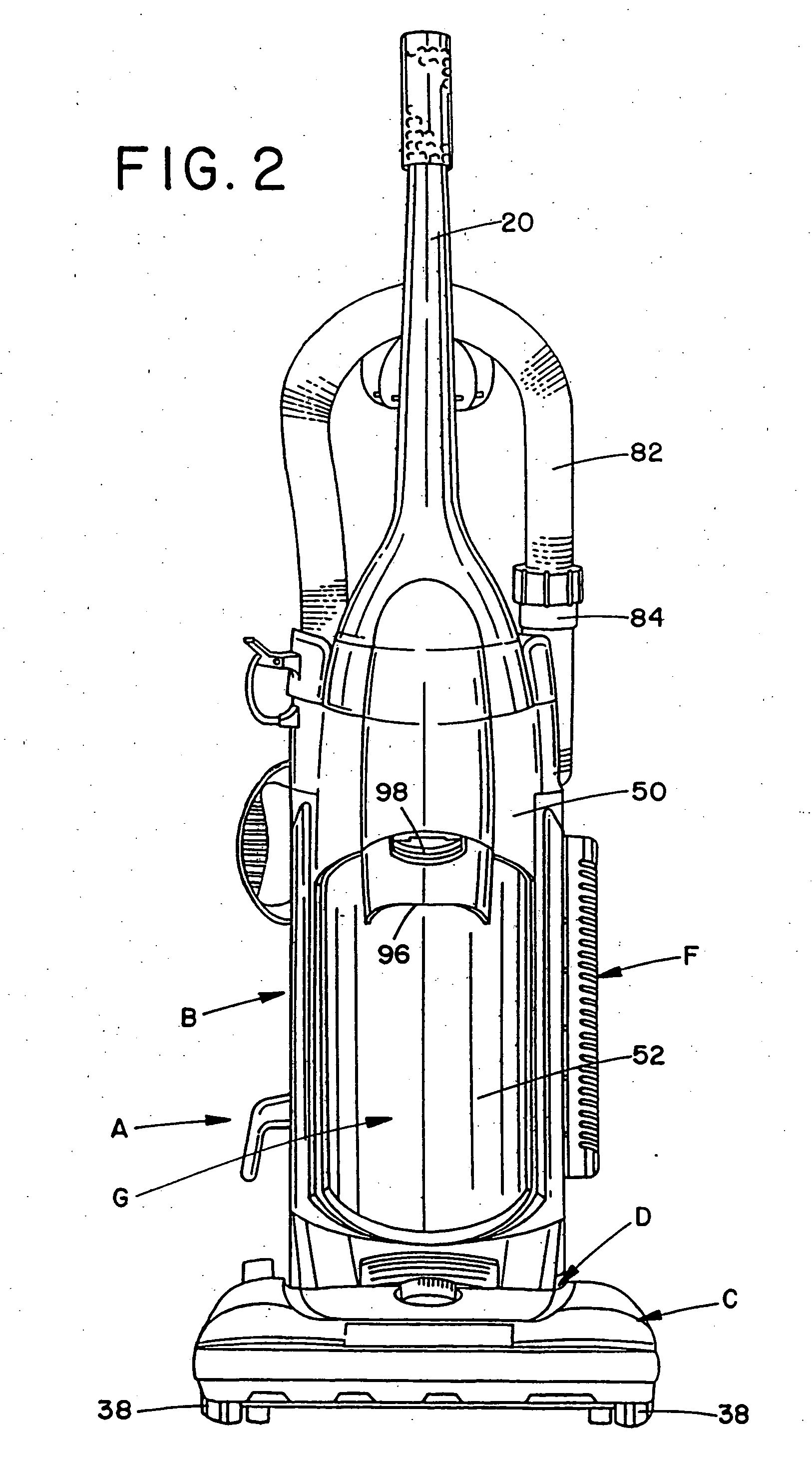
[0029] Referring now to the FIGURES, wherein the showings are for purposes of illustrating preferred embodiments of the invention only and not for purposes of limiting the same, FIGS. 1-5 illustrate an upright vacuum cleaner A including an upright housing section B and a nozzle base section C. The sections B,C are pivotally, or hingedly connected through the use of trunnions or another suitable hinge assembly D so that the upright housing section B pivots between a generally vertical storage position (as shown) and an inclined use position. Both the upright and nozzle sections B,C are preferably made from conventional materials such as molded plastics and the like. The upright section B includes a handle 20 extending upward therefrom by which an operator of the vacuum A is able to grasp and maneuver the vacuum.
[0030] During vacuuming operations, the nozzle base C travels across the floor, carpet, or other subjacent surface being cleaned. With reference now to FIG. 4, an underside 2...
PUM
| Property | Measurement | Unit |
|---|---|---|
| Flow rate | aaaaa | aaaaa |
| Shape | aaaaa | aaaaa |
| Efficiency | aaaaa | aaaaa |
Abstract
Description
Claims
Application Information
 - R&D
- Intellectual Property
- Life Sciences
- Materials
- Tech Scout
- Unparalleled Data Quality
- Higher Quality Content
- 60% Fewer Hallucinations
Browse by: Latest US Patents, China's latest patents, Technical Efficacy Thesaurus, Application Domain, Technology Topic, Popular Technical Reports.
© 2025 PatSnap. All rights reserved.Legal|Privacy policy|Modern Slavery Act Transparency Statement|Sitemap|About US| Contact US: help@patsnap.com


