Upright vacuum cleaner with cyclonic air flow

a vacuum cleaner and cyclonic technology, applied in the field of vacuum cleaners, can solve the problems of inconvenient replacement of filter elements in these units, large difficulty, and spouting of cup contents, and achieve the effect of effectively filtering residual contaminants, easy and convenient emptying, and without unduly restricting air flow

Inactive Publication Date: 2005-06-07
ROYAL APPLIANCE MFG
View PDF135 Cites 21 Cited by
  • Summary
  • Abstract
  • Description
  • Claims
  • Application Information

AI Technical Summary

Benefits of technology

[0010]One advantage of the present invention is the provision of a new and improved vacuum cleaner.
[0011]Another advantage of the invention is found in the provision of the vacuum cleaner with a cyclonic air flow chamber through which the suction air stream flows for separating dust and dirt from the air stream and for depositing the separated dust and dirt into an easily and conveniently emptied dirt cup.
[0012]Still another advantage of the present invention resides in the provision of a cyclonic air flow upright vacuum cleaner with a main filter that effectively filters residual contaminants from the suction air stream between the cyclonic air flow chamber and the motor assembly without unduly restricting air flow and without premature clogging.
[0013]Yet another advantage of the present invention is the provision of a cyclonic air flow upright vacuum cleaner in which a direct air path is provided between a suction air flow inlet, a suction air flow outlet and a vacuum source preferably positioned directly beneath the suction air flow outlet.
[0014]Still yet another advantage of the present invention is the provision of a cyclonic air flow upright vacuum cleaner with a final filter located downstream from the suction motor assembly for filtering the suction air stream immediately prior to its exhaustion into the atmosphere.
[0015]A further advantage of the present invention is the provision of a vacuum cleaner with a tangential dirty air inlet into a dust separation chamber and an axial clean air outlet from the dust separation chamber, wherein the outlet is separated from the inlet by a filter. Preferably, the dirty air inlet is located at an upper end of the dust separation chamber and the outlet is located at a lower end thereof.

Problems solved by technology

For many of the prior art cyclonic air flow vacuum cleaners, the process of emptying the dirt collection container has been found inconvenient and often resulted in the spillage of the cup contents.
Also, the replacement of filter elements in these units has not been convenient.
However, the conventional filter elements so used have caused considerable difficulty.
A conventional filter which is sufficiently fine to filter the air stream effectively, unduly restricts air flow and decreases the effectiveness of the cyclonic action.
On the other hand, a coarse filter does not effectively filter the air stream of residual contaminants.
Furthermore, conventional filter media, such as paper or fibrous media, has been found to clog readily thereby unduly decreasing air flow rates over time.

Method used


Image

  • Upright vacuum cleaner with cyclonic air flow
  • Upright vacuum cleaner with cyclonic air flow
  • Upright vacuum cleaner with cyclonic air flow

Examples


Embodiment Construction

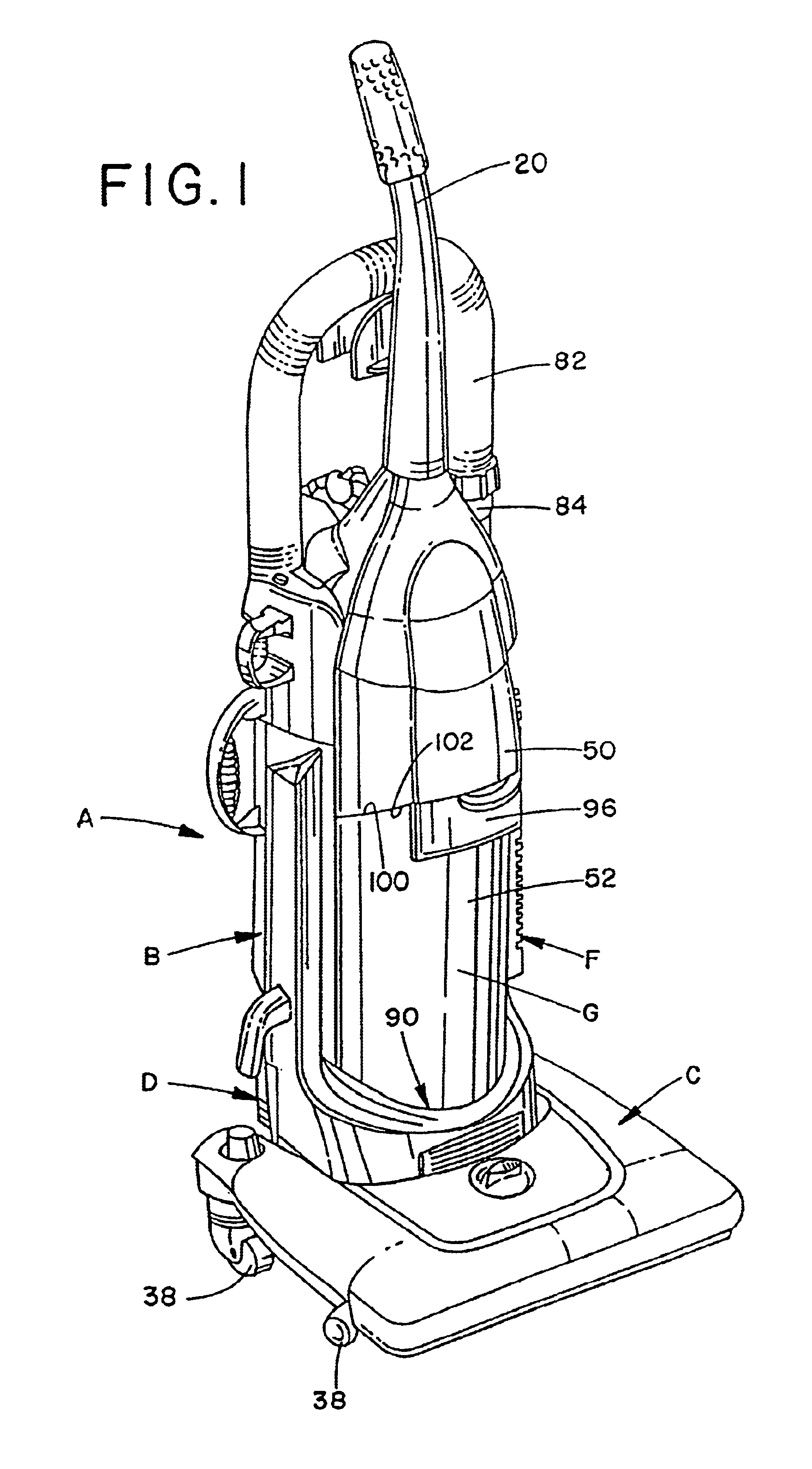
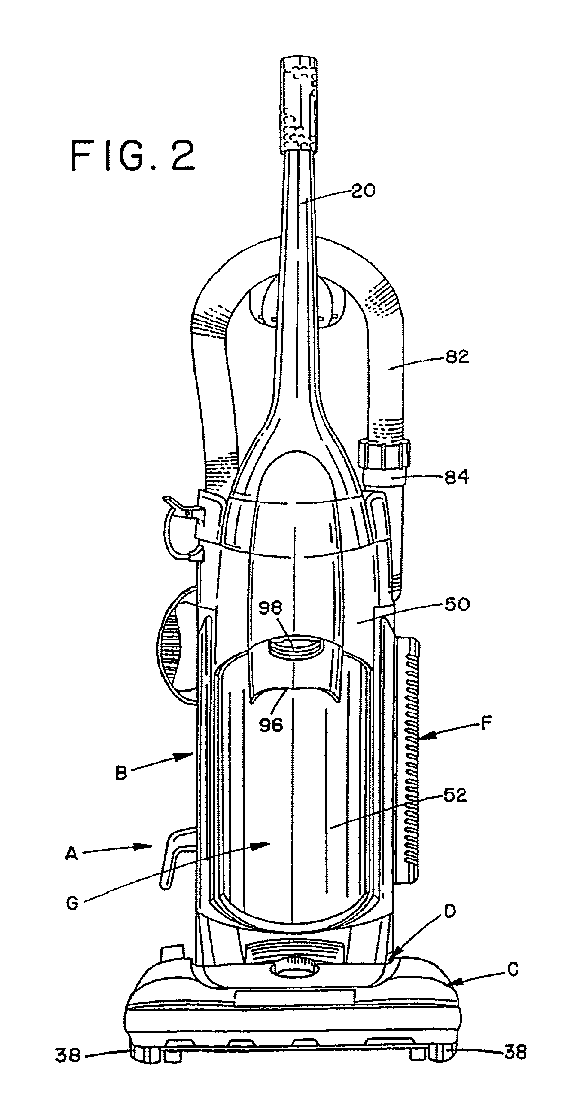
[0030]Referring now to the FIGURES, wherein the showings are for purposes of illustrating preferred embodiments of the invention only and not for purposes of limiting the same, FIGS. 1-5 illustrate an upright vacuum cleaner A including an upright housing section B and a nozzle base section C. The sections B,C are pivotally or hingedly connected through the use of trunnions or another suitable hinge assembly D so that the upright housing section B pivots between a generally vertical storage position (as shown) and an inclined use position. Both the upright and nozzle sections B,C are preferably made from conventional materials such as molded plastics and the like. The upright section B includes a handle 20 extending upward therefrom by which an operator of the vacuum A is able to grasp and maneuver the vacuum.

[0031]During vacuuming operations, the nozzle base C travels across the floor, carpet, or other subjacent surface being cleaned. With reference now to FIG. 4, an underside 24 of...


PUM

PropertyMeasurementUnit
sizeaaaaaaaaaa
shapeaaaaaaaaaa
air flow ratesaaaaaaaaaa

Abstract

An upright vacuum cleaner includes an upright housing section and a nozzle section. A cyclonic airflow dirt and dust separating chamber is defined in said upright housing section. A suction source pulls air and entrained dirt, dust, and other contaminants through a main suction opening formed in the underside of the nozzle and into the cyclonic airflow chamber. The cyclonic airflow chamber causes the suction airstream to travel in a cyclonic path such that the entrained contaminants are separated therefrom and deposited into a dirt container that defines the chamber. A main filter element filters residual contaminants from the suction airstream between the chamber and the suction source. The main filter element is preferably made from high-density polyethylene porous filter media. A final filter assembly filters the suction airstream discharged by the suction source to ensure that the air discharged into the atmosphere is contaminant free, including those contaminants introduced into the airstream by the suction source itself.

Description

[0001]This application is a continuation of U.S. application Ser. No. 09 / 818,431 which was filed on Mar. 27, 2001 now U.S. Pat. No. 6,401,295. That application, in turn, is a continuation of 09 / 216,529 filed Dec. 18, 1998, now U.S. Pat. No. 6,070,291 which issued on Jun. 6, 2000, a continuation-in-part of 09 / 122,541 filed on Jul. 24, 1998, now U.S. Pat. No. 6,026,540 which issued on Feb. 22, 2000 and a continuation-in-part of 09 / 004,999 file on Jan. 9, 1998, now U.S. Pat. No. 6,003,196 which issued on Dec. 21, 1999.BACKGROUND OF THE INVENTION[0002]The present invention relates to vacuum cleaners. More particularly, the present invention relates to upright vacuum cleaners used for suctioning dirt and debris from carpets and floors.[0003]Upright vacuum cleaners are well known in the art. The two major types of these vacuum cleaners are a soft bag vacuum cleaner and a hard shell vacuum cleaner. In the hard shell vacuum cleaner, a vacuum source generates the suction required to pull dir...

Claims


Application Information

Patent Timeline
Patent Type & Authority Patents(United States)
IPC IPC(8): A47L5/28A47L9/16A47L9/10A47L5/22A47L9/12B01D39/16B01D50/00B04C9/00B04C5/13B04C5/00
CPCA47L5/28A47L9/127A47L9/165A47L9/1666A47L9/1683B01D39/1692B01D50/002B04C5/13B04C9/00A47L9/1691Y10S55/03B04C2009/004B01D50/20
Inventor BAIR, KENNETH W.GIBBS, RICHARD C.REINDLE, MARK E.WRIGHT, MICHAEL F.
Owner ROYAL APPLIANCE MFG
Why Eureka
Try Eureka