Upright vacuum cleaner with cyclonic airflow

Inactive Publication Date: 2006-01-31
ROYAL APPLIANCE MFG
View PDF121 Cites 8 Cited by
  • Summary
  • Abstract
  • Description
  • Claims
  • Application Information

AI Technical Summary

Benefits of technology

[0015]One advantage of the present invention is the provision of a new and improved vacuum cleaner.
[0016]Another advantage of the invention is found in the proversion of a vacuum cleaner with a cyclonic airflow chamber through which the suction airflows for separating dust and dirt from the airstream and for depositing the separated dust and dirt into an easily and conveniently emptied dirt cup.
[0017]Still another advantage of the present invention resides in the provision of a cyclonic airflow upright vacuum cleaner with a main filter that effectively filters residual contaminants from the suction airstream between the cyclonic airflow chamber and the motor assembly without unduly restricting airflow and without premature clogging.
[001

Problems solved by technology

Such prior cyclonic airflow upright vacuum cleaners have not been found to be entirely effective and convenient to use.
For example, with these prior cyclonic airflow vacuum cleaners, the process of emptying dust and dirt from the cyclonic chamber dirt collection container has been found to be inconvenient, and often resulted in the spillage of the cup contents.
Likewise, with these prior units, replacement of the filter element has not been convenience.
These prior f

Method used


Image

  • Upright vacuum cleaner with cyclonic airflow
  • Upright vacuum cleaner with cyclonic airflow
  • Upright vacuum cleaner with cyclonic airflow

Examples


Example

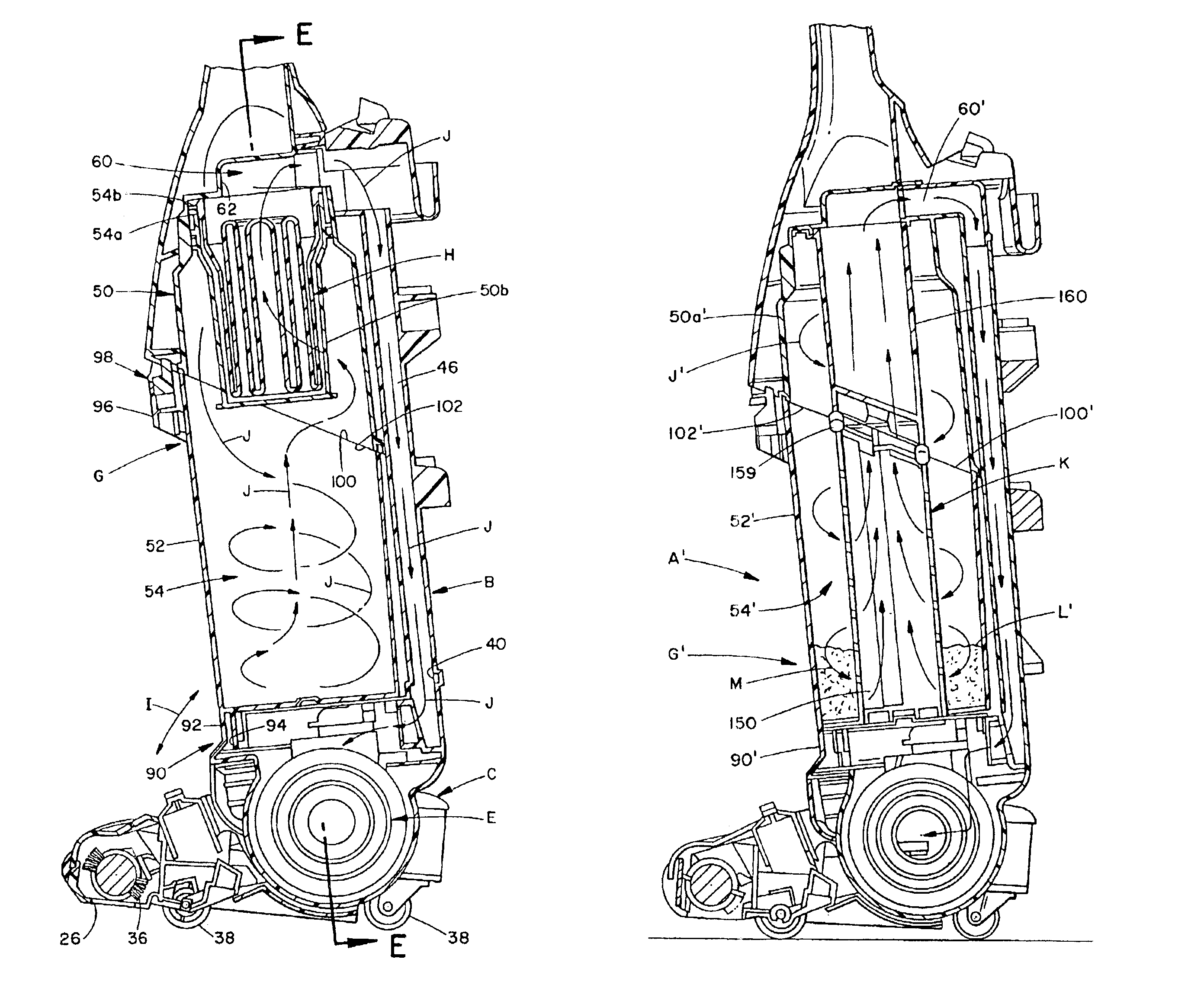
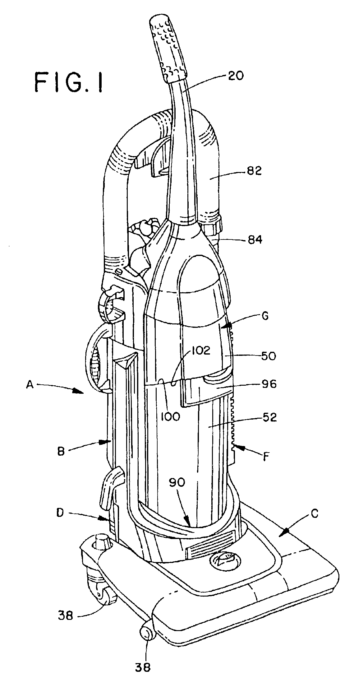
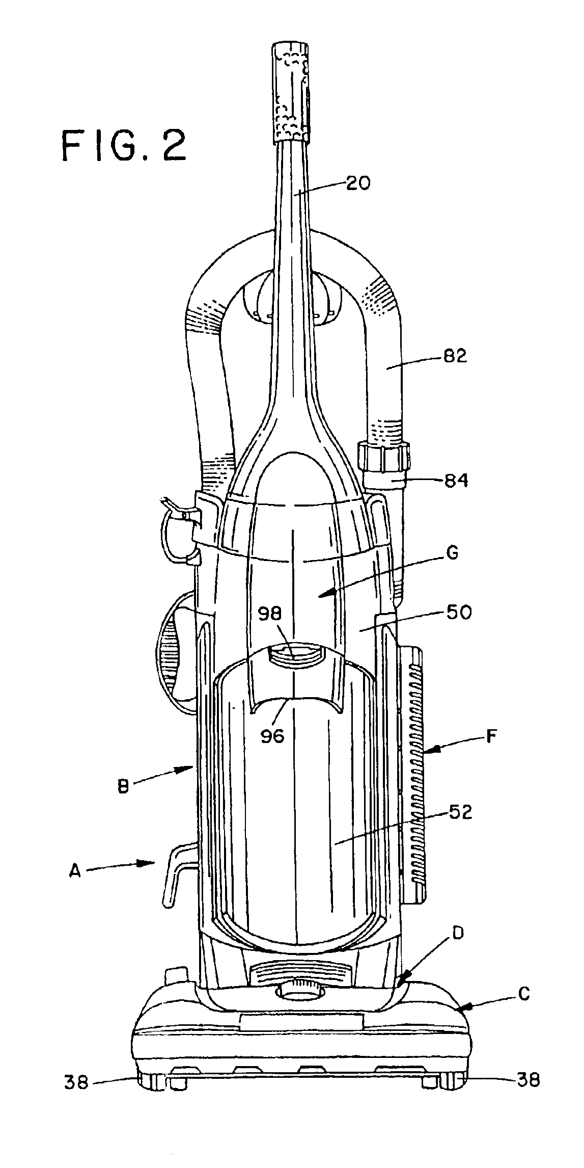
[0047]Referring now to the FIGURES, wherein the showings are for purposes of illustrating preferred embodiments of the invention only and not for purposes of limiting the same, FIGS. 1-6 illustrate and upright vacuum cleaner A including an upright housing section B and a nozzle base section C. The sections B,C are pivotally or hingedly connected through the use of trunnions or another suitable hinge assembly D so that the upright housing section B pivots between a generally vertical storage position (as shown) and an inclined operative position. Both the upright and nozzle sections B,C are preferably made from conventional materials such as molded plastics and the like. The upright section B includes a handle 20 extending upward therefrom by which an operator of the vacuum A is able to grasp and maneuver the vacuum.

[0048]During vacuuming operations, the nozzle base C travels across the floor, carpet, or other subjacent surface being cleaned. The underside 24 (FIG. 6) of the nozzle i...


PUM

PropertyMeasurementUnit
Pore sizeaaaaaaaaaa
Pore sizeaaaaaaaaaa
Diameteraaaaaaaaaa

Abstract

An upright vacuum cleaner (A) includes an upright housing section (B) and a nozzle section (C). A cyclonic airflow dirt and dust separating chamber (54) is defined in said upright housing section. A suction source (E) pulls air and entrained dirt, dust, and other contaminants through a main suction opening (26) formed in the underside (24) of the nozzle and into the cyclonic airflow chamber (54). The cyclonic airflow chamber causes the suction airstream to travel in a cyclonic path such that the entrained contaminants are separated therefrom and deposited into a dirt container (52) that defines the lower portion of the chamber (54). A main filter element (11) filters residual contaminants from the suction airstream between the chamber and the suction source. The main filter element is preferably made from high-density polyethylene porous filter media. A final filter assembly (F) filters the section airstream discharged by the suction source to ensure that the air discharged into the atmosphere is contaminant free, including those contaminants introduced into the airstream by the suction source itself.

Description

[0001]This is a continuation-in-part of application Ser. No. 09 / 044,999, filed Jan. 9, 1998.BACKGROUND OF THE INVENTION[0002]The present invention relates to vacuum cleaners. More particularly, the present invention relates to upright version cleaners used for suctioning dirt and debris from carpets and floors.[0003]Upright vacuum cleaners are ubiquitous. They are known to include an upper portion having a handle, by which an operator of the vacuum cleaner may grasp and maneuver the cleaner, and a lower cleaning nozzle portion which travels across a floor, carpet, or other surface being cleaned. The upper portion is often formed as a rigid plastic housing which encloses a dirt and dust collecting filter bag, although the upper portion may simply be an elongated handle with the filter bag, and an external cloth bag, being hung therefrom. The cleaning nozzle is hingedly connected to the upper handle portion such that the upper portion is pivotable between a generally vertical upright ...

Claims


Application Information

Patent Timeline
IPC IPC(8): A47L9/10A47L9/16A47L5/28A47L9/12B01D39/16B01D50/00B04C5/13B04C9/00
CPCA47L5/28A47L9/127A47L9/165A47L9/1666A47L9/1683B01D39/1692B04C5/13B04C9/00B04C2009/004Y10S55/03B01D50/20
Inventor WRIGHT, MICHAEL F.THUR, CHARLES J.CIPOLLA, MARK E.LATIMER, BRETT A.STEPHENS, PAUL D.
Owner ROYAL APPLIANCE MFG
Why Eureka
Try Eureka