Method of laying cords of a reinforcement structure for tires

a technology of reinforcement structure and filament, which is applied in the direction of tire beads, tyres, vehicle components, etc., can solve the problems of difficult modulation of sidewall and/or bead characteristics, tire described in this document do not have the conventional upturn, etc., and achieves the effects of increasing the modulus, increasing the density of the filament, and reducing the number of filaments

Inactive Publication Date: 2005-02-10
MICHELIN RECH & TECH SA
View PDF7 Cites 15 Cited by
  • Summary
  • Abstract
  • Description
  • Claims
  • Application Information

AI Technical Summary

Benefits of technology

[0020] Given the high laying speeds and the reduced spaces between the filaments, the laying of multiple cords with a single head is particularly advantageous in preventing the cords from being too close to each other, or even touching over certain portions of paths. It is furthermore easier to lay the filaments regularly than if they are laid separately.
[0068] In the case of a tire manufactured using such an automated process in which the different constituent elements are laid turn by turn directly on a core, the profile of which corresponds substantially to that of the final product, the action of laying groups of cords comprising two (or more) cords is particularly advantageous. For example, the result is a great reduction in the laying time for the reinforcement structure.

Problems solved by technology

However, there are nowadays tires which do not, properly speaking, comprise “plies” or “bead wires” in accordance with the preceding definitions.
Furthermore, the tires described in this document do not have the conventional upturn of the carcass ply around a bead wire.
In the current art, it is quite difficult to modulate the characteristics of the sidewall and / or of the bead.
Furthermore, the reinforcements which are arranged in this part of the tire always inevitably have a discontinuity: at the level of the radially upper end of the carcass upturn, there is a change without transition into a zone devoid of this carcass upturn, which zone is therefore inevitably less rigid.
Finally, the cost demands are becoming increasingly harsh and require productivity gains which are becoming increasingly difficult to obtain, taking into account the ceaselessly increasing technicality of the products.

Method used


Image

  • Method of laying cords of a reinforcement structure for tires
  • Method of laying cords of a reinforcement structure for tires
  • Method of laying cords of a reinforcement structure for tires

Examples


Embodiment Construction

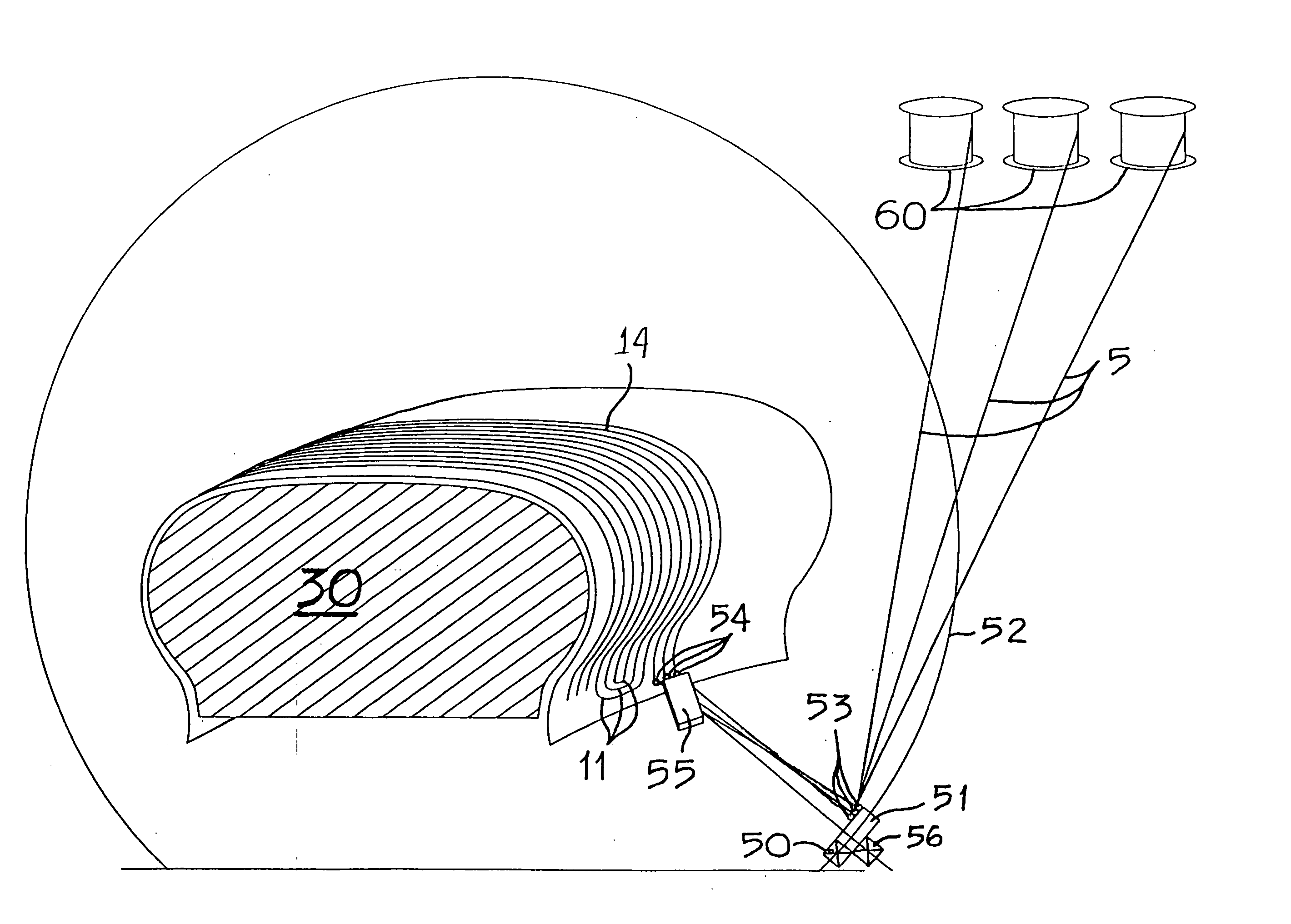
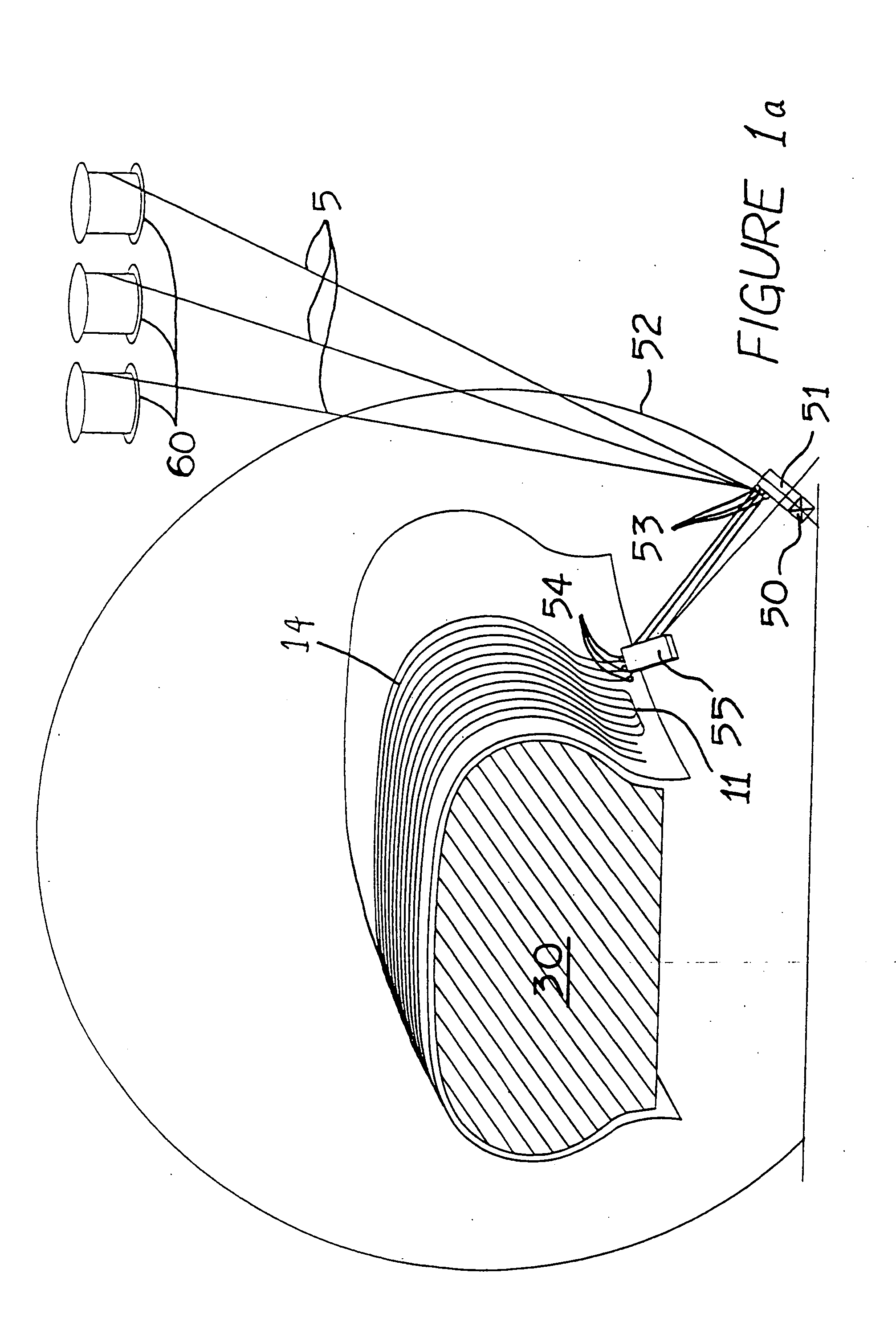
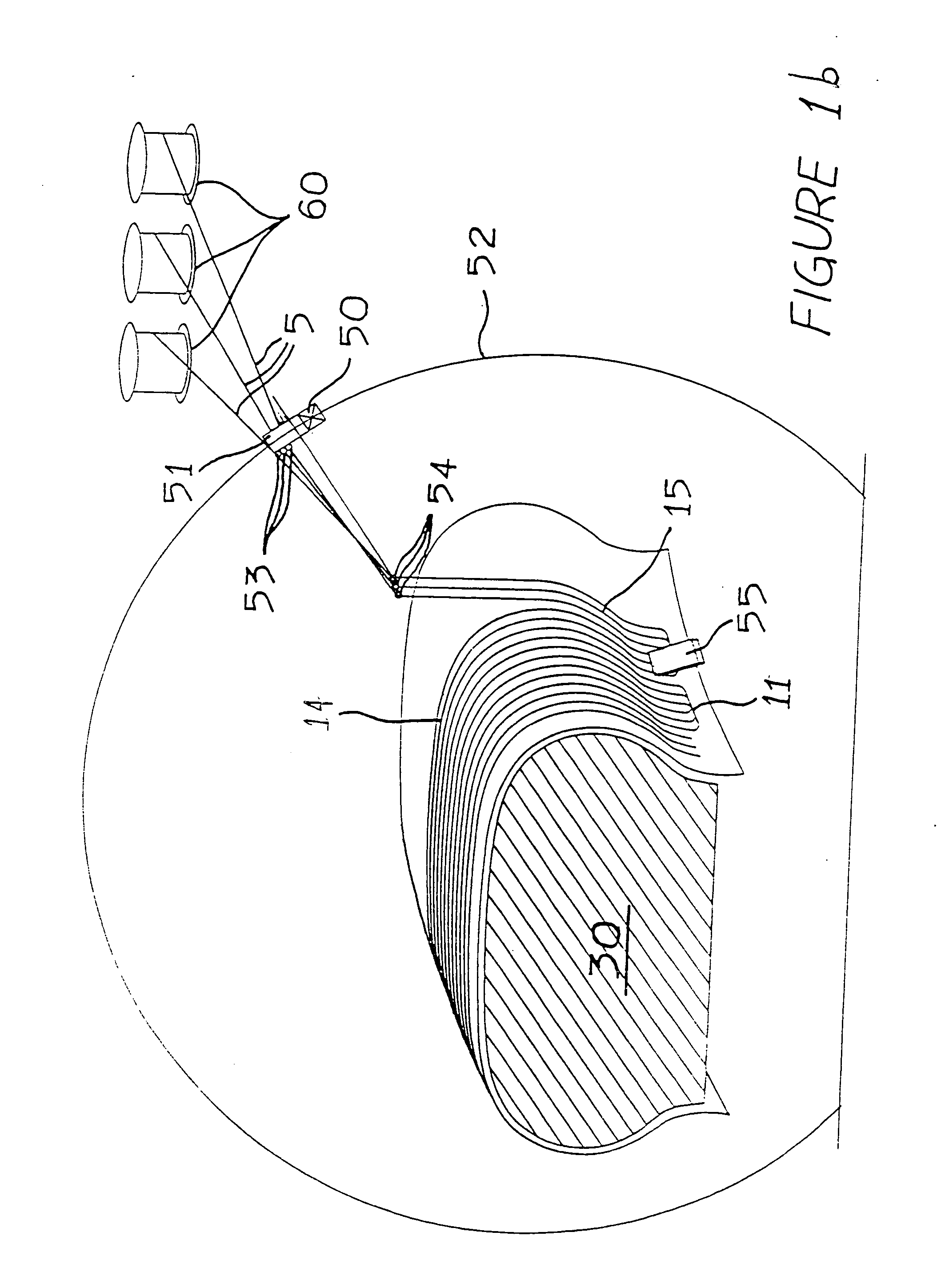
[0101]FIGS. 1a to 1d illustrate an example of a method which permits the manufacture of tires such as those described in the following figures (in particular FIGS. 3 to 14), with the substantially simultaneous laying of at least two cords 50. Using this method facilitates obtaining portions of substantially parallel paths. Storage or supply means make it possible to bring in two, three (or even more) cords which are to be applied to a first layer of rubber mix formed substantially in the image of the profile of the final product. Before application, the cords are arranged in the immediate vicinity of each other at distances corresponding substantially to the distance provided between the cords of one and the same group. For application of the cords against the mix, the laying means moves in space, for example from one bead to the other, along the path which the cords to be laid have to follow in the tire.

[0102] Thus, a group of cords is guided by a laying means for application alon...


PUM

PropertyMeasurementUnit
angleaaaaaaaaaa
angleaaaaaaaaaa
angleaaaaaaaaaa

Abstract

A method of laying cords of a carcass-type reinforcement structure on a tire, consisting of arranging at least two filaments on a tire blank so that at least one first and one second filament form on one hand, at the level of the crown and the sidewalls, a series of transverse portions extending substantially from one bead of the tire to the other, in which a single laying head is used which permits substantially simultaneous laying of said at least first and second filaments. The head is advantageously arranged relative to the blank of the tire such that the filaments form at least a portion of substantially parallel paths relative to each other. The sections of substantially parallel paths are preferably applied substantially between the crown and the beads.

Description

FIELD OF INVENTION [0001] The present invention relates to a method for laying reinforcement cords or filaments for tires. More particularly, it relates to the arrangement and the configuration of the reinforcement structure in the sidewalls, the beads and the crown zone of the tire; it also relates to the anchoring of the carcass cords in the bead and the reinforcements of different portions of the bead or the sidewall. BACKGROUND OF INVENTION [0002] The reinforcement of tires is currently constituted by one or more plies, conventionally referred to as “carcass plies”, “crown plies”, etc. This method of designating reinforcements derives from the manufacturing process, consisting of producing a series of semi-finished products in the form of plies, provided with frequently longitudinal cord reinforcements, which are subsequently assembled to build a tire. [0003] The plies are produced flat, with large dimensions, and are subsequently cut according to the dimensions of a given produ...

Claims


Application Information

Patent Timeline
Patent Type & Authority Applications(United States)
IPC IPC(8): B60C15/00B29D30/10B29D30/16
CPCB29D30/10Y10T152/10855B29D2030/1678B29D30/1635
Inventor PANNING, NATHAN
Owner MICHELIN RECH & TECH SA
Why Eureka
Try Eureka